

Mechanical optical switch
- Summary
- Abstract
- Description
- Claims
- Application Information
AI Technical Summary
Benefits of technology
Problems solved by technology
Method used
Image

Examples
Embodiment Construction
Switch Overview
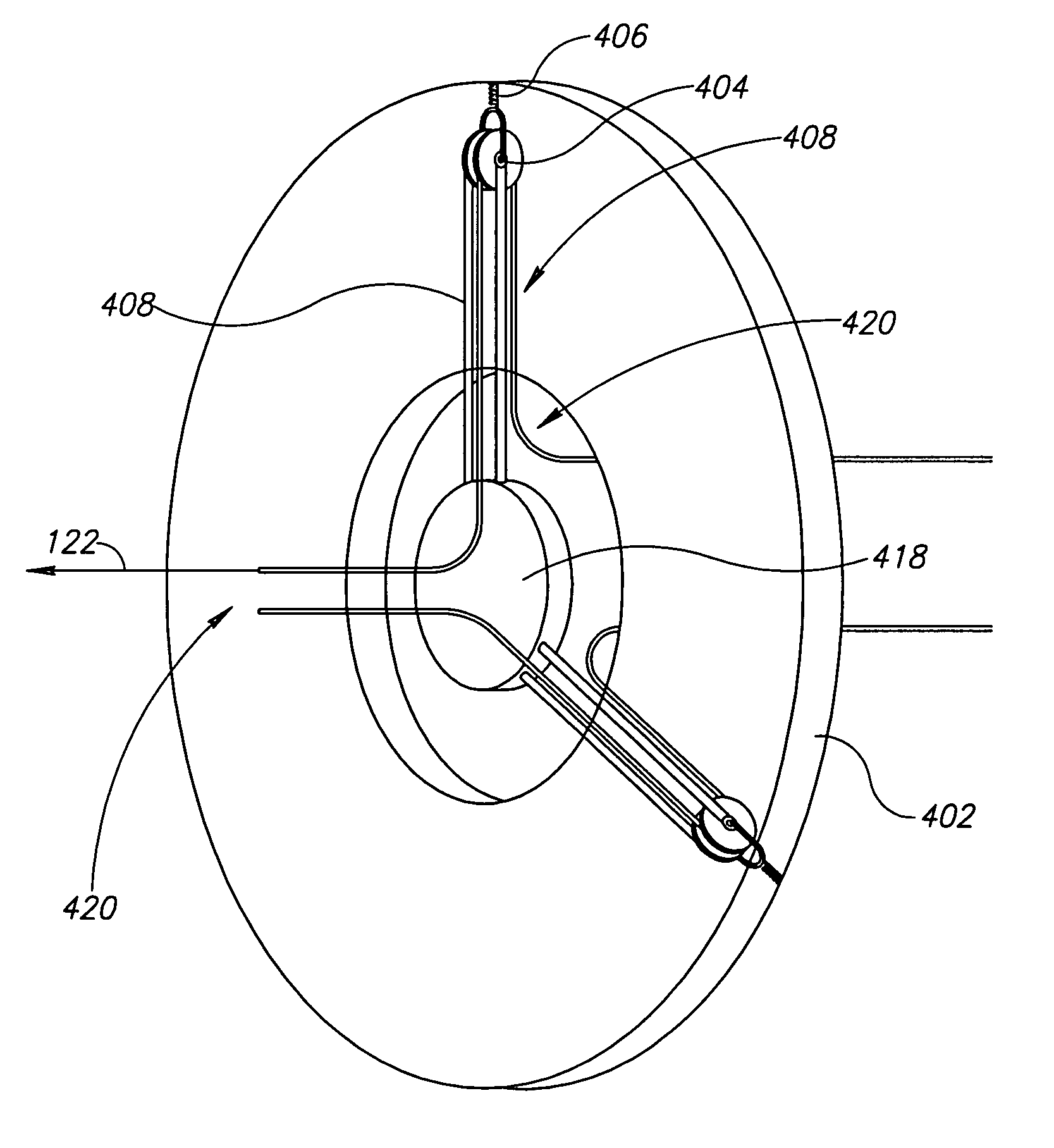
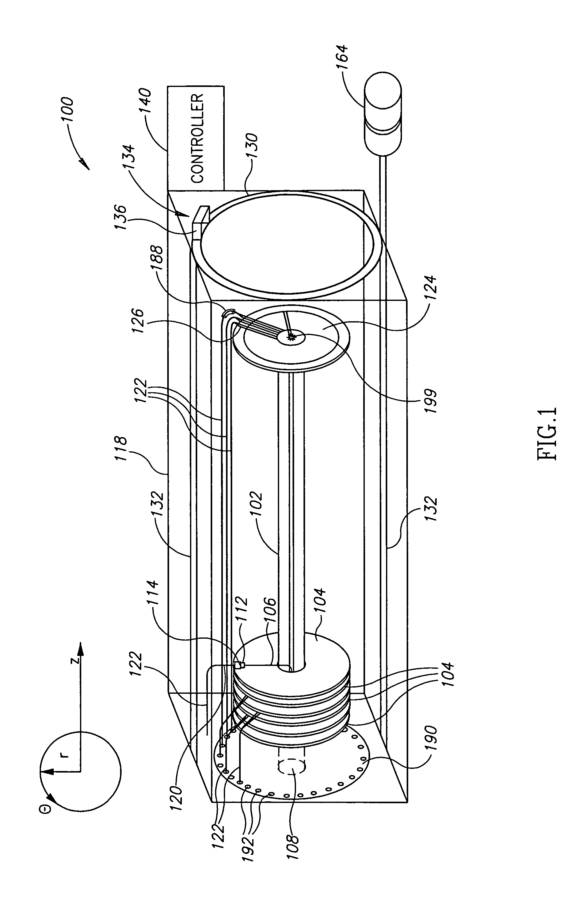
[0046]FIG. 1 is a schematic illustration of a mechanical optical fiber switch 100, in accordance with an exemplary embodiment of the invention. Switch 100 includes a central shaft 102 which leads a plurality of input optical fibers 106, only one of which is shown, from an entrance 108 to a plurality of respective rotary disks 104, located at fixed positions along shaft 102, but rotatable around the shaft 102. A plurality of output optical fibers 122 are arranged around the perimeter of disks 104 free to move along an axis (referred to herein as the Z-axis) parallel to shaft 102, but confined to predetermined positions around the perimeters of rotatable disks 104, in order to avoid tangling of the fibers. The lines along which the output optical fibers 122 move define together the curved surface of a cylinder.
[0047]Optionally, each input optical fiber 106 has an optical connector 112 at its end, as are generally provided at the ends of optical fibers. An optical fiber ...
PUM
 Abstract
Description
Claims
Application Information