Method and device for reducing the carbon dioxide content in a dead volume

a carbon dioxide and dead volume technology, applied in the field of methods for reducing dead volumes, can solve the problems of significant low pressure and limitations in the volume which can be evacuated, and achieve the effect of simple, effective and safe anesthesia

Inactive Publication Date: 2010-10-19
MAQUET CRITICAL CARE
View PDF11 Cites 41 Cited by
  • Summary
  • Abstract
  • Description
  • Claims
  • Application Information

AI Technical Summary

Benefits of technology

[0015]By suctioning a volume of gas out of the dead volume, removing carbon dioxide from that gas and then returning the cleaned gas to the dead volume, a simple and effective reduction of the carbon dioxide content is obtained in the mechanical dead volume. The gas can be suctioned out continually as well as intermittently.
[0018]By the use of a flow generator which generates a gas flow between an outlet associated with the dead volume and an inlet associated in series with the flow generator, a simple and effective device is obtained for reducing the carbon dioxide content in the mechanical dead volume.
[0020]In regard only to parts of the mechanical dead volume outside the patient, relatively coarse tubes can be used and the flow generator does not need to be designed to generate a vacuum or high pressure differences to generate a sufficient gas flow. The flow generator can be driven continually with a cancelled minute volume or work intermittently, synchronized with expirations or parts of expirations.
[0021]To reduce the risk of contamination, bacterial filters can be introduced in series with the flow generator and the absorber, between these and the outlet and inlet, respectively.
[0026]A particularly beneficial application of the device according to the invention is in an anesthesia apparatus. The design provides a compact, effective and safe anesthesia apparatus.

Problems solved by technology

A drawback with the known method is that limitations exist in the volume which can be evacuated.
This results in significant low pressure being required to bring about a sufficient stream of evacuated gas.

Method used


Image

  • Method and device for reducing the carbon dioxide content in a dead volume
  • Method and device for reducing the carbon dioxide content in a dead volume
  • Method and device for reducing the carbon dioxide content in a dead volume

Examples


first embodiment

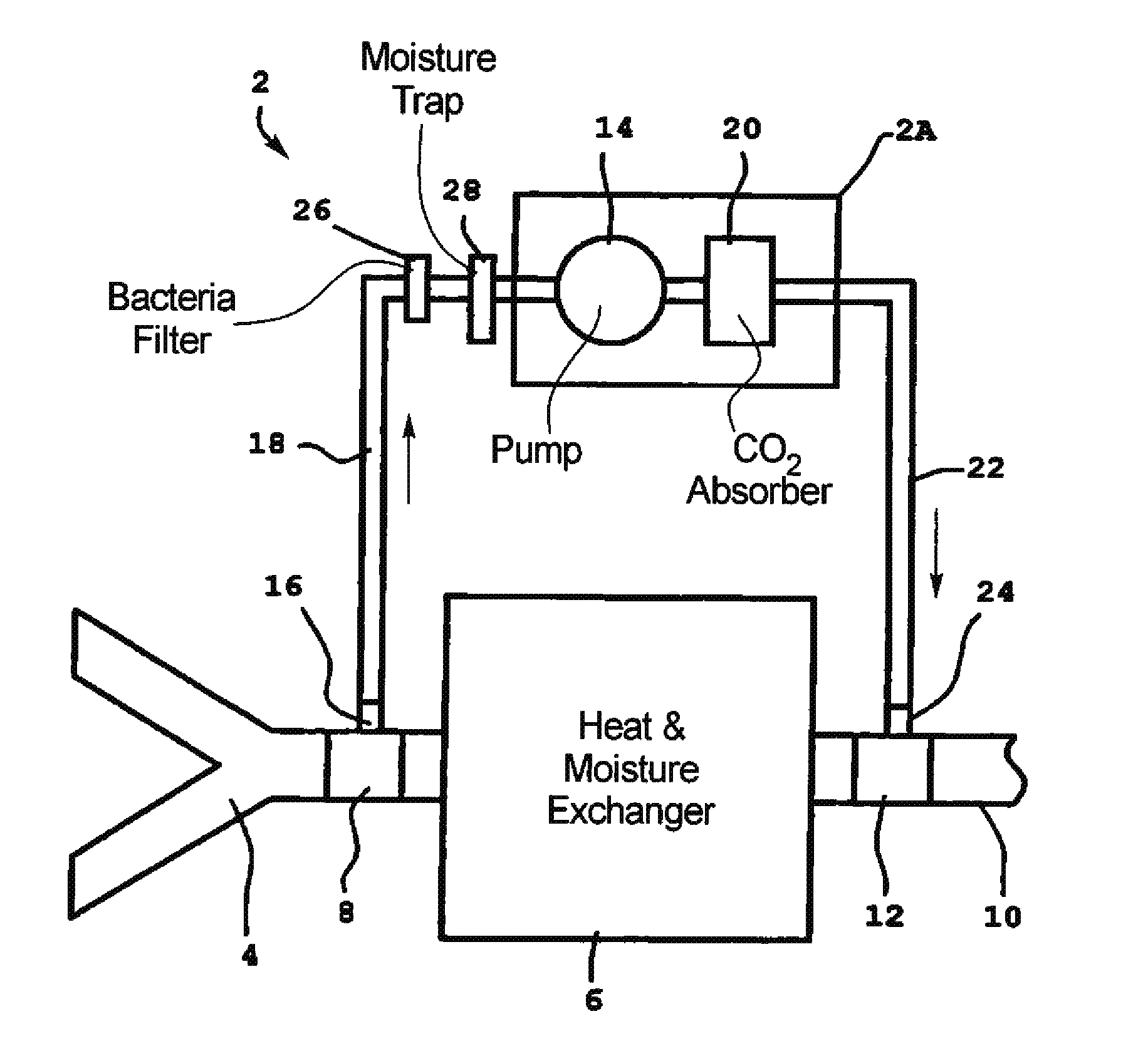
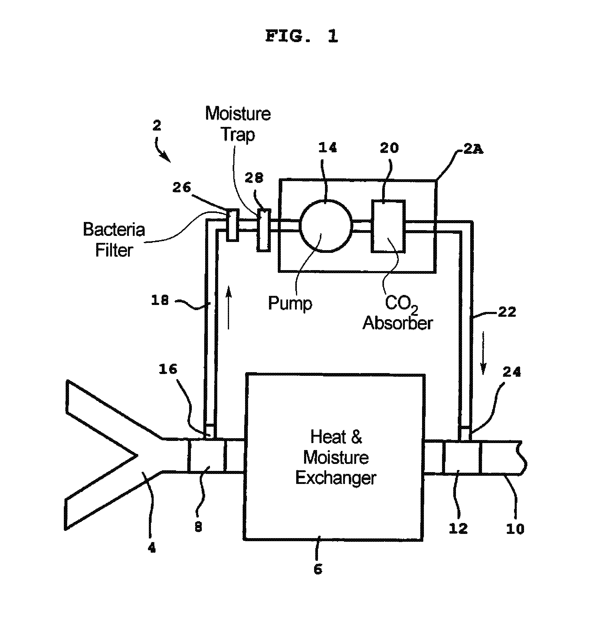
[0030]In FIG. 1 a device 2 according to the invention is shown. The device 2 is coupled between a y-piece 4 via a first adapter 8 and a moisture and heat exchanger 6 and a patient connection 10 via a second adaptor 12.

[0031]The y-piece 4 is connected to a ventilator (not shown) or another conventional respiratory apparatus with separate flow passages for inspiration and expiration. Since such apparatuses are well known and the invention is not principally directed to functions or designs for them, they do not need to be described in this context.

[0032]It can be noted that the Y-piece 4 in this regard represents all known connections for respiratory apparatuses, for example coaxial connections such as Bain-system, etc.

[0033]The patient connection 10 can be any conventional patent connection, for example, tracheal tube, tracheotomy tube, tracheostomy tube, or a non-invasive face mask. These components are also well known and do not need to be described further in this context.

[0034]Th...

second embodiment

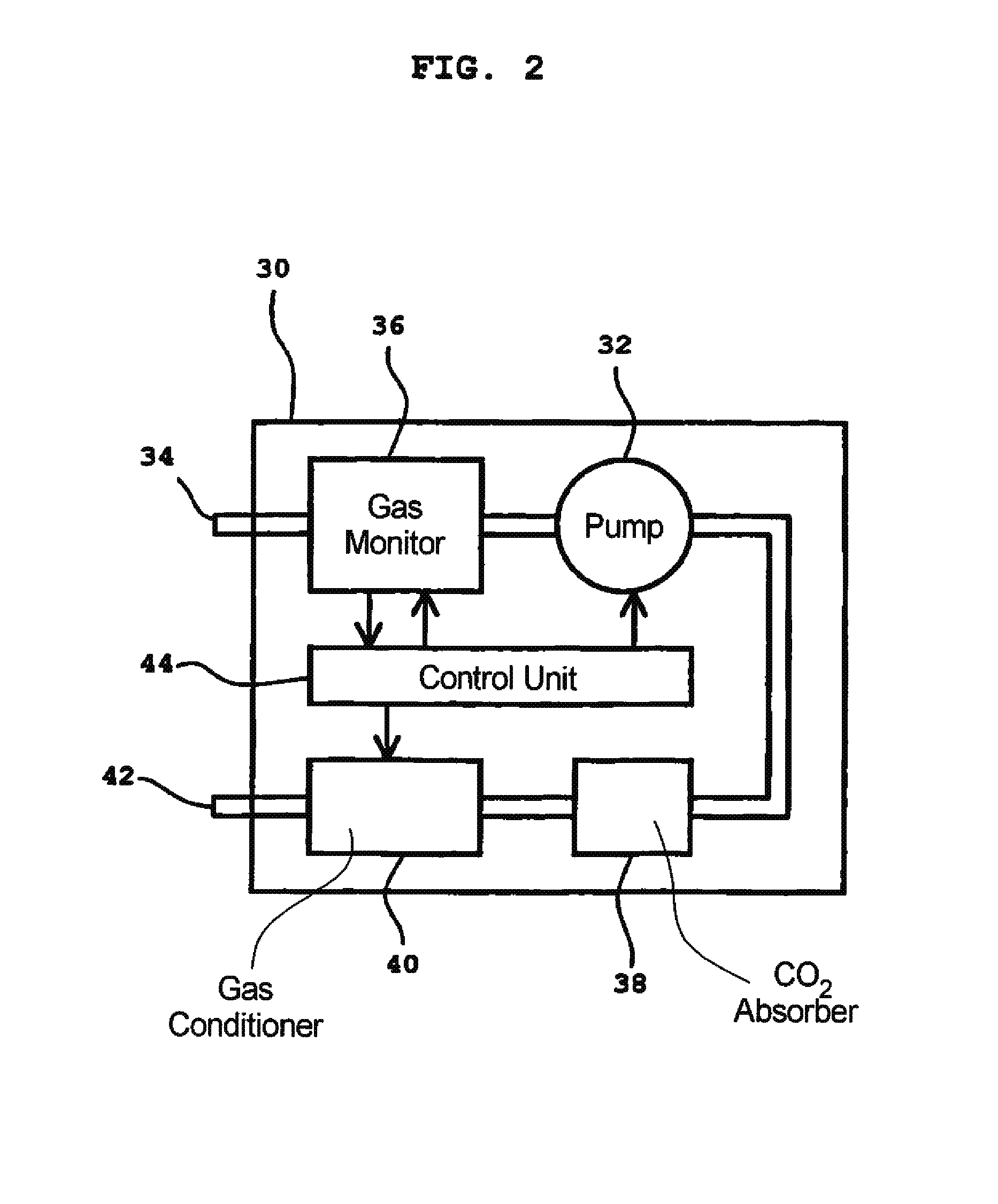
[0052]In FIG. 2 a device 30 according to the invention is shown. The device 30 in this case consists of a pump 32 which sucks gas from a first connection 34, which is connectable to a dead volume (not shown). The device 30 further contains a gas monitor 36 for qualitative and / or quantitative analysis of the gas, a CO2 absorber 38, a gas conditioner 40, a second connection 42 (connectable to the dead volume) and a control unit 44.

[0053]In the device 30 the gas that is suctioned out of the dead volume is analyzed. The analysis can be directed to one or many of the components in the gas, for example carbon dioxide, oxygen or a trace gas. The measured result is transferred to the control unit 44.

[0054]The control unit 44 can control the pump 14, the gas conditioner 40 and the gas monitor 36. By measuring the carbon dioxide content in the gas, the pump's 32 sucking effect can be regulated based on the carbon dioxide concentration, that is, essentially synchronized with expirations. The p...


PUM


Abstract

In a method and device for reducing the carbon dioxide content in a dead volume intended for connection to the respiratory system of a patient, and an anesthesia apparatus embodying such a device, a flow of gas is generated from an outlet associated with the dead volume and the gas is conducted through a carbon dioxide absorber, and the gas after passing through the carbon dioxide absorber is returned to an inlet associated with the dead volume.

Description

BACKGROUND OF THE INVENTION[0001]1. Field of the Invention[0002]The present invention concerns a method for reducing a dead volume in an apparatus designed to be connected to the respiratory system of a patient.[0003]The present invention is also directed to a device for reduction of dead volume in an apparatus designed to be connected to the respiratory system of a patient.[0004]2. Description of the Prior Art[0005]As a rule, when an apparatus is to be connected to the respiratory system of a patient, a machine dead volume is introduced. This dead volume results in carbon dioxide in expired gas from the patient being returned to the respiratory system with the following inspiration.[0006]“Apparatus” as used herein relates to all respiratory apparatuses which can be connected to the respiratory system to condition respiratory gas, facilitate breathing, support breathing, control breathing, etc. Typical apparatuses of this type are respirators and ventilators for respiratory therapy ...

Claims


Application Information

Patent Timeline
Patent Type & Authority Patents(United States)
IPC IPC(8): A62B23/02A61M16/00A61M16/10A61M16/22
CPCA61M16/0057A61M16/22A61M16/1065A61M2230/43A61M16/0063A61M16/0833
Inventor PSAROS, GEORGIOS
Owner MAQUET CRITICAL CARE
Why Eureka
Try Eureka