Compact valve

a valve body and compact technology, applied in the field of compact valves, can solve the problems of high production cost, inability to return to the shape originally memorized, and inability to control the valve's control performance, so as to increase the reliability of connection of lead wires for energizing which are connected to the electrodes, reduce production cost, and reduce the effect of reducing production cos

Inactive Publication Date: 2010-10-19
MATSUSHITA ELECTRIC WORKS LTD
View PDF21 Cites 37 Cited by
  • Summary
  • Abstract
  • Description
  • Claims
  • Application Information

AI Technical Summary

Benefits of technology

[0006]An object of the present invention is to solve the problems mentioned above, and to provide a compact valve in which an orifice is sealed by transforming a wire formed of a shape memory alloy by heating, and which maintains resistance to deterioration and increases reliability, by preventing occurrence of deterioration with age of a shape memory alloy because of enabling elastically to transform an overall length of a movable structure including a sealing body, and to reduce a stress in heating of the wire by the elastic deformation of the movable structure.
[0007]In order to achieve the above mentioned object, an aspect of the present invention is a compact valve that opens and closes a fluid path with utilizing transformation of a shape memory ally due to energization heating, characterized by that the compact valve comprises: a stationary structure of a cylindrical shape having an orifice that constitutes the fluid path; a moving structure that contacts an inner periphery of the stationary structure, and has a sealing member freely movable to seal the orifice; a wire formed of a shape memory alloy to move the moving structure; and a first electrode and a second electrode to hold the wire and to energize the wire, and wherein the moving structure is configured so that a length thereof is elastically variable, and is movable to seal the orifice by varying a length of the wire due to energization heating to the wire; and the moving structure elastically transforms when sealing the orifice, and thereby, a stress that the wire receives can be reduced.
[0008]According to the present invention, a cushion effect by elastic deformation of the moving structure, a stress applied to the wire, that is, the shape memory alloy can be reduced in the energization heating to the wire. Thereby, it is possible to prevent the overload due to an excess pressure to the shape memory alloy, so that repeatability of memorized shape of the shape memory alloy is not deteriorated, and thus, durability and high reliability of the valve can be obtained.

Problems solved by technology

However, when an overload is applied to the shape memory alloy in a state of memorized shape, the repeatability of recovery may be damaged, and thus, it cannot return to the shape originally memorized due to deterioration with age by repetition of the overloads.
On this account, in a valve using a shape memory alloy as an actuator, when repeatability of recovery of the shape memory alloy is deteriorated, control performance of the valve falls off.
In addition, the valve shown in above mentioned Patent Publication needs two shape memory alloys as the actuator, so that configuration thereof becomes complex and it causes high cost of production.
Since the shape memory alloy is formed in the coil spring shape, so that a profile of the valve becomes larger, and thus, downsizing of the valve is difficult.
In addition, when thickening a diameter of a wire of the coil spring to obtain a predetermined force, responsiveness in heat radiation becomes worse due to increase of heat capacity of the coil spring.
Since temperature distribution occurs in a folded portion of the wire, durability of the valve is easily deteriorated by thermal stress.
When the wire works to operating limit, the shape memory alloy suffers from overloads, and thus, deterioration with age occurs.

Method used


Image

  • Compact valve
  • Compact valve
  • Compact valve

Examples


first embodiment

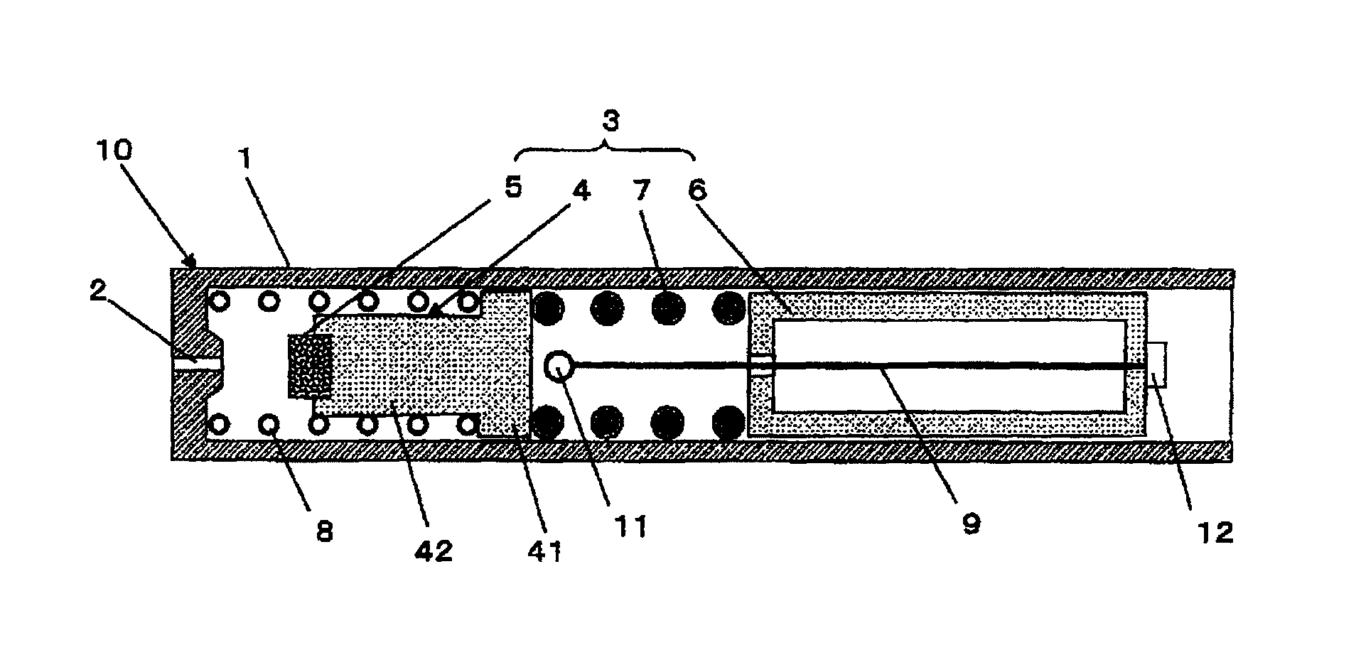
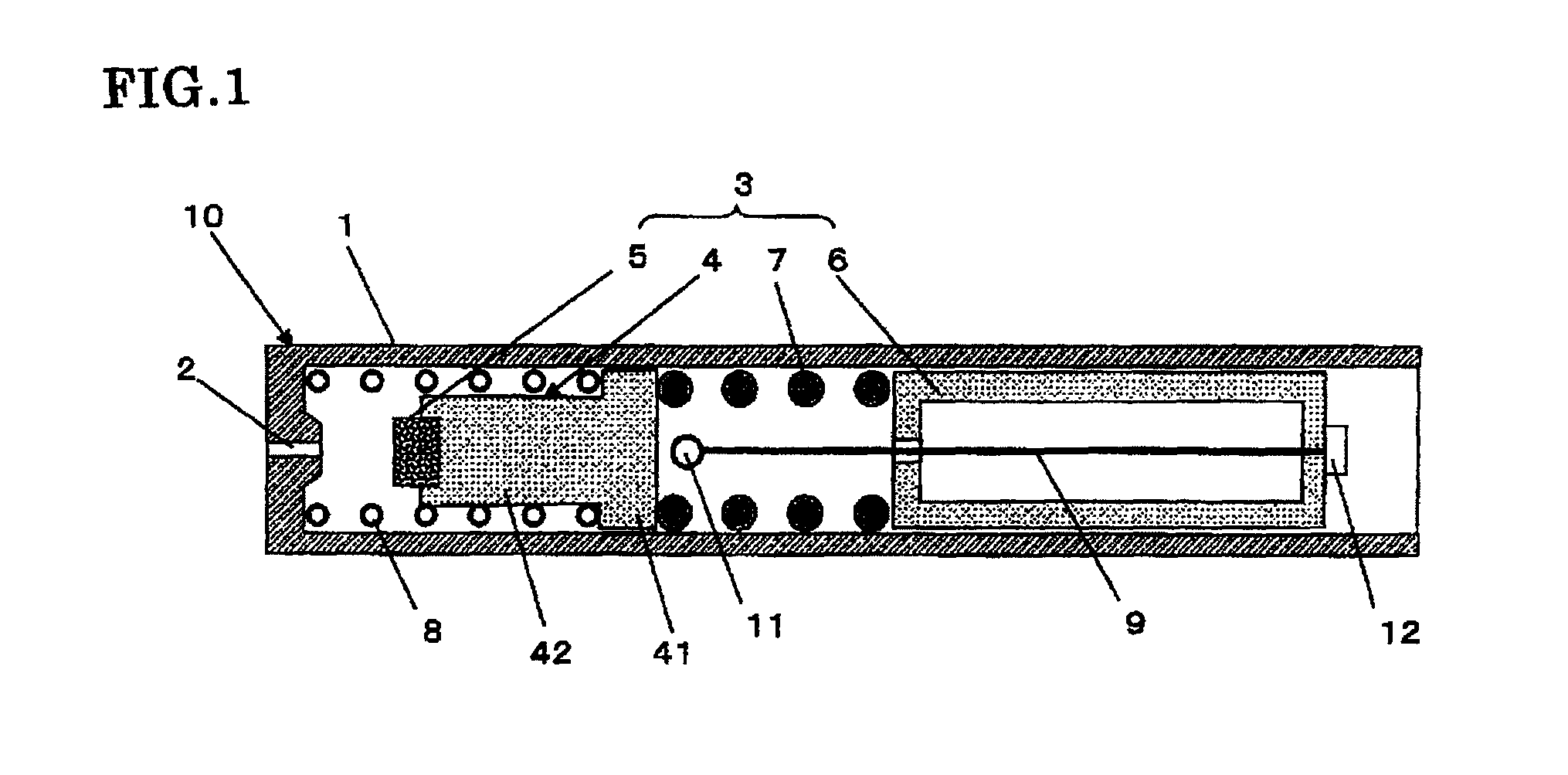
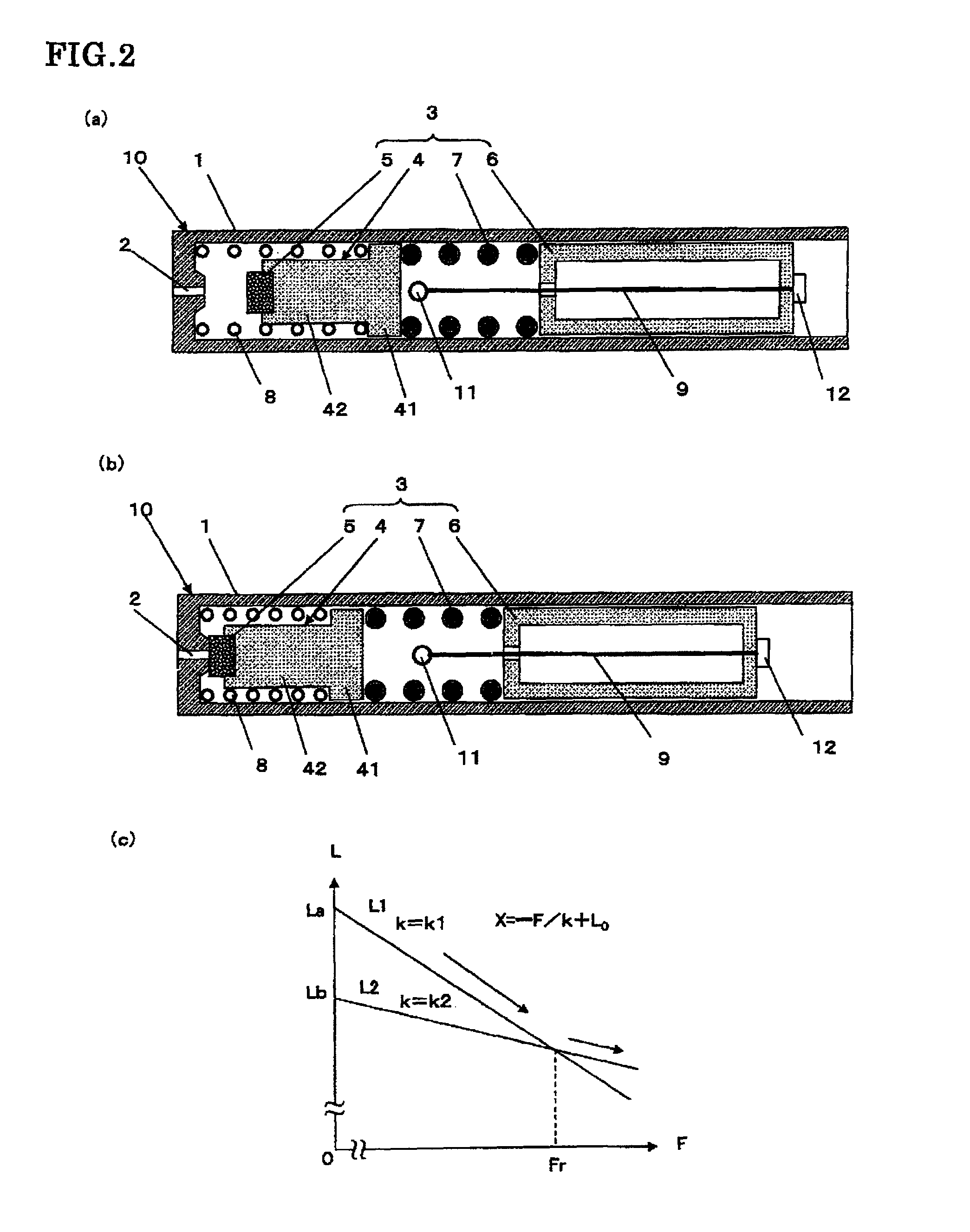
[0034]A compact valve in accordance with the present invention is described below with reference to FIG. 1, FIGS. 2(a), 2(b) and 2(c). The compact valve 10 of this embodiment utilizes a phenomenon that a shape memory alloy is transformed by heating due to current supply for opening and closing a fluid path. It comprises a cylindrical shaped guide pipe (stationary structure) 1 which is formed of a metal or resin; an orifice 2 formed of a metal or a resin that constitutes the fluid path built-in the guide pipe 1; a moving valve body (moving structure) 3 that seals the orifice 2 in freely movable state; a wire 9 made of a shape memory alloy (or a shape memory resin, a shape memory rubber, or the like) that drives the moving valve member 3; and a biasing coil 8. The moving valve body 3 has a first moving portion 4, a second moving portion 6, a sealing portion (sealing member) 5 which is formed of a resin or a rubber for sealing the orifice 2 and provided at a front end of the first movi...

third embodiment

[0051]Subsequently, a compact valve in accordance with the present invention is described with reference to FIGS. 4(a), 4(b) and 4(c). The compact valve 10 of this embodiment is essentially the same as those in the above mentioned embodiments, but it is different that a sealing portion 5 of a moving valve body 3b is formed of an elastic material.

[0052]The moving valve body 3b comprises a moving portion 4b formed of a metal or a resin and a sealing portion 5 to seal an orifice 2 at an end thereof, and the sealing portion 5 is formed of an elastic material such as a resin or a rubber. Since the moving valve body 3b has the sealing portion 5 formed of the elastic material, it becomes an elastic member as a whole. Hereupon, an elastic coefficient of the moving valve body 3b as a whole is designated by a symbol k3.

[0053]In the above mentioned configuration, when the wire 9 formed of the shape memory alloy is energized to fever, the wire 9 is contracted and the moving portion 3b moves due...

fourth embodiment

[0056]Subsequently, compact valves in accordance with a fourth embodiment are described with reference to FIGS. 5(a), 5(b) and 5(c). These figures are respectively show different examples. The compact valves 10 in this embodiment are essentially the same as those in the above mentioned embodiments, but moving valve bodies (moving structures) 3c, 3d and 3e reach comprise a spring member.

[0057]In the example shown in FIG. 5(a), the moving valve body (moving structure) 3c comprises a moving portion 4a of a cylindrical shape having a cylindrical column portion 45 at a front end thereof, a sealing portion 5 to seal an orifice 2 provided at a front end of the cylindrical column portion 45, an electrode supporting plate 13 that supports a moving electrode 12, and a coil spring (spring member) 7a that is provided between the electrode supporting plate 13 and an end of the moving portion 4c. The moving valve body 3c has elasticity due to the coil spring 7a.

[0058]In the above mentioned confi...


PUM


Abstract

A compact valve using a shape memory alloy comprises: a moving valve body that contacts an inner periphery of a guide pipe having an built-in orifice, is freely movable and has a sealing portion to seal the orifice; a biasing coil provided between the orifice and the moving valve body; and a wire formed of a shape memory alloy and held between a stationary electrode of the guide pipe and a moving electrode of the moving valve body. The orifice is sealed by moving the moving valve body due to transformation of the shape memory alloy by heating the wire. The moving valve body is enabled to be elastically deformable by providing a coil spring to reduce a stress, so that an overload to the moving valve body due to contraction of the wire is absorbed by elastic deformation of the moving valve body. Thereby, the overload to the shape memory alloy is reduced to prevent deterioration of repeatability of memorized shape, to increase durability and reliability of the valve.

Description

TECHNICAL FIELD[0001]The present invention relates to a compact valve which utilizes a shape memory alloy to control open and close of paths for various fluids such as air, liquid, or the like.BACKGROUND ART[0002]As for such a compact valve, it is conventionally known that an actuator for a valve body that opens and closes an orifice is formed of a shape memory alloy, and the valve body is displaced by applying electric current to the actuator, as shown in Japanese Laid-Open Patent Publication No. 05-99369, for example. In such a control valve, in order to increase sealing property of the orifice, it is necessary to increase a pressure applied to the orifice, so that the shape memory alloy serving as the actuator contracts after contacting the orifice and further pressurizes the orifice in closing operation of the valve. In addition, the orifice is additionally pressurized due to variation of the shape memory alloy in manufacturing process thereof. The shape memory alloy receives a ...

Claims


Application Information

Patent Timeline
Patent Type & Authority Patents(United States)
IPC IPC(8): F16K31/02
CPCF16K31/025F16K99/0001F16K99/0038F16K99/0044F16K99/0007C08L2201/12Y10T137/7737F16K99/0034
Inventor SAITOH, AKIHIKODOHNO, SHIGERUGOTO, TAKAOYAMAMOTO, KEN
Owner MATSUSHITA ELECTRIC WORKS LTD
Why Eureka
Try Eureka