Low noise valve assembly

a valve assembly and low noise technology, applied in the direction of valve operating means/release devices, combustion air/fuel air treatment, machines/engines, etc., can solve the problems of noise being a whooshing noise, ticking noise, noise noise, etc., to eliminate or substantially reduce the creation of objectionable noise during operation, the effect of reducing the creation of nois

Active Publication Date: 2010-10-19
FORD GLOBAL TECH LLC
View PDF21 Cites 8 Cited by
  • Summary
  • Abstract
  • Description
  • Claims
  • Application Information

AI Technical Summary

Benefits of technology

[0013]According to another, more specific aspect of the invention, a canister purge valve assembly is provided for an internal combustion engine of the type fueled by volatile liquid fuel stored in a fuel tank. The assembly comprises a fuel vapor inlet tube extending from the fuel tank and terminating in a generally annular chamber. An outlet tube has a generally annular valve seat disposed within the inlet tube chamber and a flow channel extending centrally through the valve seat. The flow channel has a minimum throat diameter immediately downstream of the valve seat. The outlet tube is operatively connected to a vacuum inlet of the engine. An elastomeric valve is disposed in the inlet tube chamber for movement toward and away from a closed condition in direct contact with the valve seat. The valve includes an insert body that is spatially segregated from direct contact with the outlet tube while partially filling the flow channel when the valve is in its closed condition. The insert body has a generally circular base with a diameter that is larger than the throat diameter. Furthermore, the insert body extends from the base toward a terminal tip, with the distance between the base and the tip being controlled by the relationship 1.0≦D / H≦2.0, where D is the diameter of the base and H is the normal distance between the base and the tip. A valve assembly manufactured according to the subject invention eliminates aerodynamic stagnation and separation from the gas flow immediately downstream of the valve thereby eliminating or substantially reducing the creation of objectionable noises during operation.

Problems solved by technology

One is a ticking noise caused by the opening and closing of the valve.
Particularly, the ticking noise is found to occur if the vapor line mounting is made at the front of the floor pan.
The other type of noise is a whooshing noise that is caused by the flow of gases through the valve as they are sucked into the engine intake manifold.
The whooshing sound is considered to be particularly troublesome.
Noise, vibration and harshness (NVH) concerns during vehicle operation can greatly affect customer satisfaction with the vehicle.
A typical complaint, however, is that this predominant whooshing noise is heard when the vehicle hood is open and a person is standing near the engine.
An objectionable noise also occurs during the closing event of the valve, which creates a popping noise that reverberates through the vapor lines.
This popping noise phenomenon happens during normal operation, where the engine intake manifold pulls a vacuum on the outlet tube side of the valve.
Mechanical analysis, including flow analysis and testing, have demonstrated that failures are caused by flow-induced instability in the valve.
The stagnation and separation zones under the valve are significantly unstable and result in local pressure pulsations and noise.
During the energy conversion process, i.e., momentum to potential energy, energy dissipation contributes to the aerodynamic noise and mechanical valve vibrations.
Such proposals are somewhat effective, but do not eliminate the problem and add costs to the overall system.
Such muffler and sound dampening strategies are not well suited to practical, real world applications.
Furthermore, cost and design complexity issues severely frustrate such approaches.

Method used


Image

  • Low noise valve assembly
  • Low noise valve assembly
  • Low noise valve assembly

Examples


Embodiment Construction

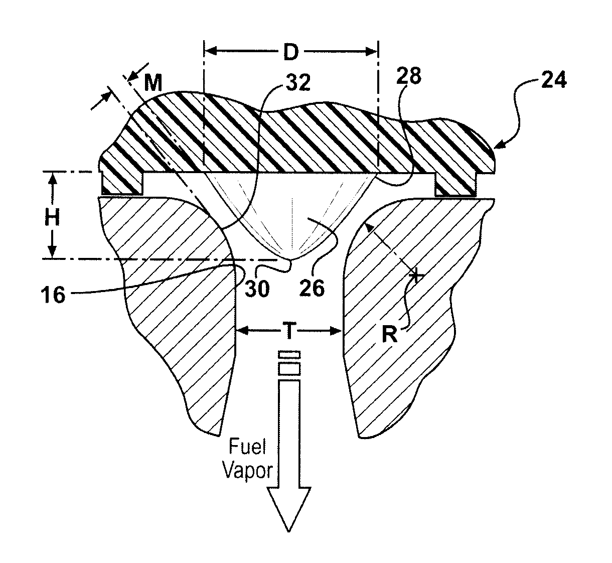
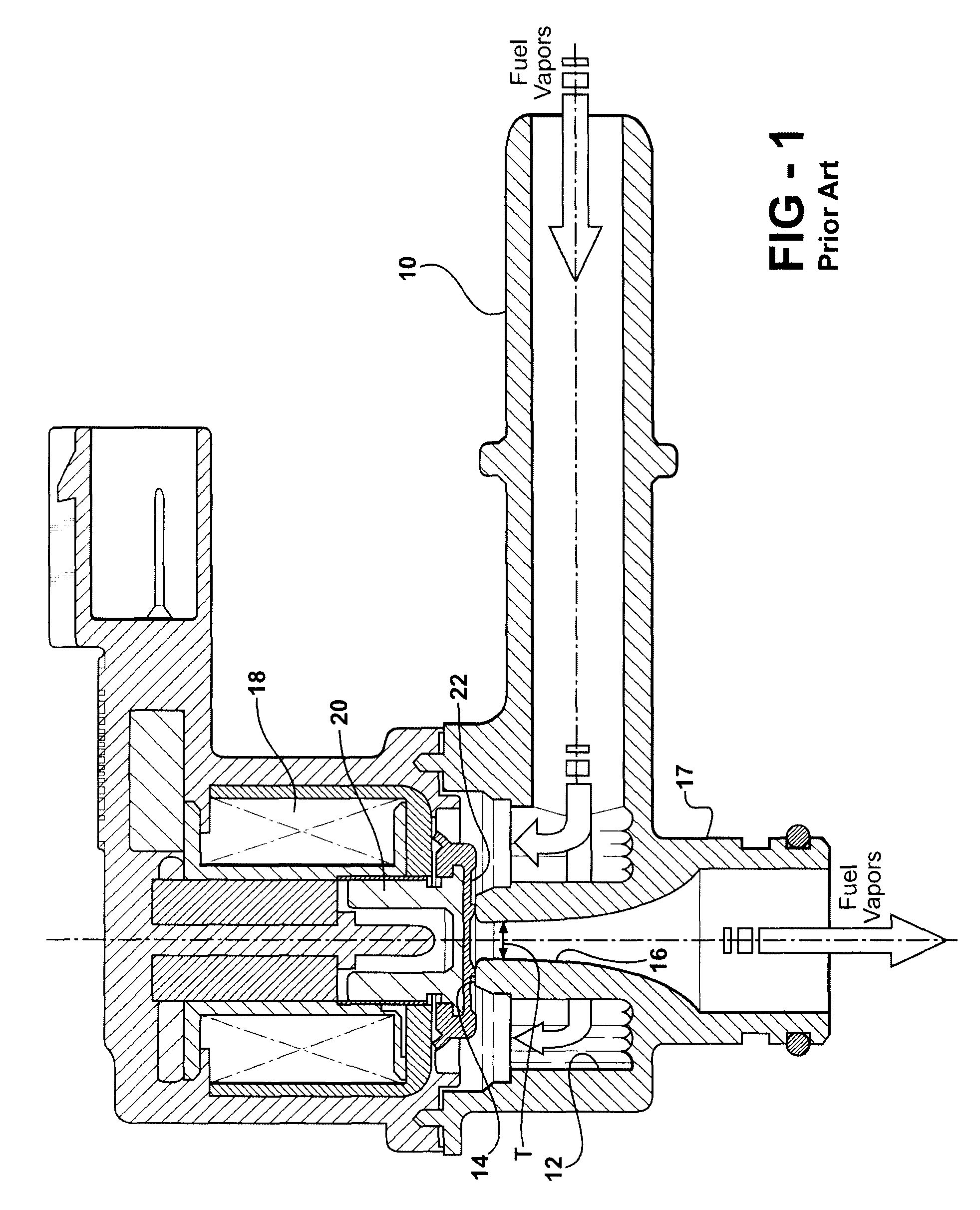
[0023]Referring to the Figures, wherein like numerals indicate like or corresponding parts throughout the several views, a typical prior art CPV valve is generally shown at FIG. 1 including an inlet tube 10 which, although not shown, is of the type which extends in fluid conducting fashion to a fuel tank containing volatile liquid fuel. Commonly, a collection canister will be disposed in line between the CPV valve and the fuel tank. The inlet tube terminates in a generally annular chamber 12. An outlet tube 17 has a generally annular valve seat 14 disposed within the inlet tube chamber 12. Flow channel 16 extends centrally through the valve seat 14. The flow channel 16 has a minimum throat diameter T immediately downstream of the valve seat 14. The throat diameter T eventually widens in diffuser-like fashion as the gas flow is ultimately routed to the vacuum inlet of an internal combustion engine. An electromagnetic valve assembly includes an electromagnetic coil 18 that surrounds a...


PUM


Abstract

A low noise valve assembly (24) mitigates noise induced by near sonic gas flow encountering stagnant flow in the region of the valve (24). An inlet tube (10) terminates in an annular chamber (12). An outlet tube (17) has a generally annular valve seat (14) disposed within the chamber (12). The valve (24) moves toward and away from a closed condition in direct contact with the valve seat (14). The valve (24) includes an insert body (26) that is spatially segregated from direct contact with the outlet tube (17) while partially filling the flow channel (16) of the outlet tube (17) when the valve (24) is in its closed condition. The insert body (26) has a generally circular base with a diameter that is larger than the throat diameter (T), which is the internal diameter of the flow channel (16) adjacent the valve (24).

Description

CROSS REFERENCE TO RELATED APPLICATIONS[0001]None.BACKGROUND OF THE INVENTION[0002]1. Field of the Invention[0003]The subject invention relates generally to an electromagnetically actuated valve assembly, and more particularly toward a canister purge valve assembly of the type used for controlling the flow of fuel vapors from a fuel tank to an internal combustion engine.[0004]2. Related Art[0005]A canister purge valve (CPV) is an electromagnetically driven valve that allows fuel vapors that are collected from the fuel tank in a canister to be purged by suction through an engine intake manifold under certain operating modes and conditions. A typical prior art CPV is illustrated in FIG. 1. As shown, the construction includes an inlet tube that leads to a chamber. An outlet tube has an upstanding portion that resides in the chamber and presents a generally annular valve seat for contact by a poppet valve having a flat valve bottom surface to seal the valve seat when in a closed conditi...

Claims


Application Information

Patent Timeline
Patent Type & Authority Patents(United States)
IPC IPC(8): F02M25/08
CPCF16K1/36F16K1/42F16K47/04F16K31/0655Y10T137/8085
Inventor DONG, MIKEPLYMALE, KEVINUSMAN, MOHAMMAD
Owner FORD GLOBAL TECH LLC
Why Eureka
Try Eureka