Atraumatic gastrointestinal anchor

a gastrointestinal and gastrointestinal technology, applied in the field of atraumatic gastrointestinal anchors, can solve the problems of increasing the risk of anchor injury, affecting and affecting the healing effect of the anchor, so as to promote radial expansion and contraction of the device, and the thickness of the tube can be altered

Active Publication Date: 2010-10-19
GI DYNAMICS
View PDF390 Cites 88 Cited by
  • Summary
  • Abstract
  • Description
  • Claims
  • Application Information

AI Technical Summary

Benefits of technology

[0005]To anchor within a lumen, anchors generally apply at least some outward force directed toward the inner walls of the lumen. Depending upon the application, the anchoring force can vary from a minimal force (e.g., to hold hooks in position) to a more substantial force (e.g., forming an interference fit). In biological applications the inner walls of a lumen typically contain tissue that is soft and particularly vulnerable to irritation. Thus, in these applications a greater force increases the risk that the anchor will lead to trauma by way of irritation or even tissue damage.
[0008]The intraluminal anchor also includes an elongated anchoring member that, when implanted, provides at least two different radial forces at respective positions along its length. These different radial forces act differently upon respective portions of the natural bodily lumen when the device is implanted therein. Namely, at least one of the radial forces is primarily a securing force adapted to anchor within the natural bodily lumen. The other radial force is a transitional force adapted to mitigate damage to the natural bodily lumen. Further, when implanted, the intraluminal anchor defines an interior lumen allowing for continued functioning of the natural bodily lumen.
[0012]In some embodiments having plural anchoring elements, at least one of the anchoring elements can be formed from an elongated wire. The elongated wire can be formed in any suitable shape, such as a helix or an oscillating (i.e., wave-shaped) pattern. The wave-shaped pattern distributes the respective radial force over the length of the anchoring element while also improving performance of the anchoring element's respective radial expansion and contraction.
[0013]To further enhance its anchoring performance, the intraluminal anchor can include at least one external barb adapted to penetrate tissue of the natural bodily lumen. The external barb is located at a predetermined position along the length of the intraluminal anchor, the corresponding radial force acting to press the barb into the tissue. For example, in a multi-anchoring element embodiment, the at least one external barb can be coupled to one of the anchoring elements. The force of the coupled anchoring element then acts to hold the barb within the tissue.
[0015]Preferably, the anchor is radially collapsible for endoscopic insertion. The intraluminal anchor can also include a drawstring to facilitate repositioning and / or removal. The drawstring, for example, can be provided at a proximal end of the device and be adapted for engagement by a removal device, such as a hook. The drawstring, when engaged, can be pushed or pulled by the removal device, in opposition to the stationary intraluminal anchor, to at least partially collapse at least part of the intraluminal anchor. With a reduced diameter, the device can be removed through, or repositioned within, the natural bodily lumen. In some embodiments, at least a portion of the device is drawn into a retrieval hood, sheath, or overtube prior to removal.

Problems solved by technology

Unfortunately, stiff anchors can traumatize surrounding tissue.
As this securing force can be substantial, tissue damage at the proximal and distal ends of the anchor are likely to occur.
In biological applications the inner walls of a lumen typically contain tissue that is soft and particularly vulnerable to irritation.
Thus, in these applications a greater force increases the risk that the anchor will lead to trauma by way of irritation or even tissue damage.
Unfortunately, the high mobility of the intestine and the nature of the forces acting on material within the intestine (i.e., peristalsis) complicate anchoring there.

Method used


Image

  • Atraumatic gastrointestinal anchor
  • Atraumatic gastrointestinal anchor
  • Atraumatic gastrointestinal anchor

Examples


Embodiment Construction

[0032]A description of preferred embodiments of the invention follows.

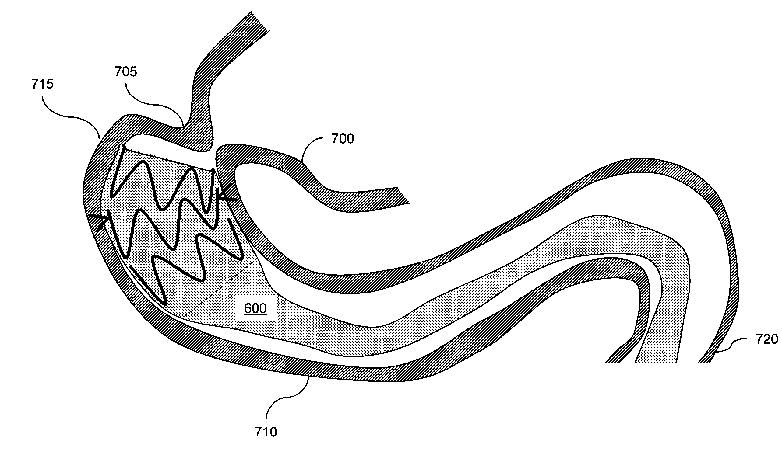
[0033]An anchor is adapted for anchoring within a natural bodily lumen while allowing continued functionality of the lumen and providing minimal trauma to the surrounding anatomy. Such an anchor provides a securing force acting upon the surrounding anatomy to hold the anchor fast, even in the presence of anticipated biological forces. For example, the securing force would hold a gastrointestinal anchor in position even in the presence of peristalsis. Anchoring against such forces, however, may require substantial securing force that could otherwise damage the surrounding tissue.

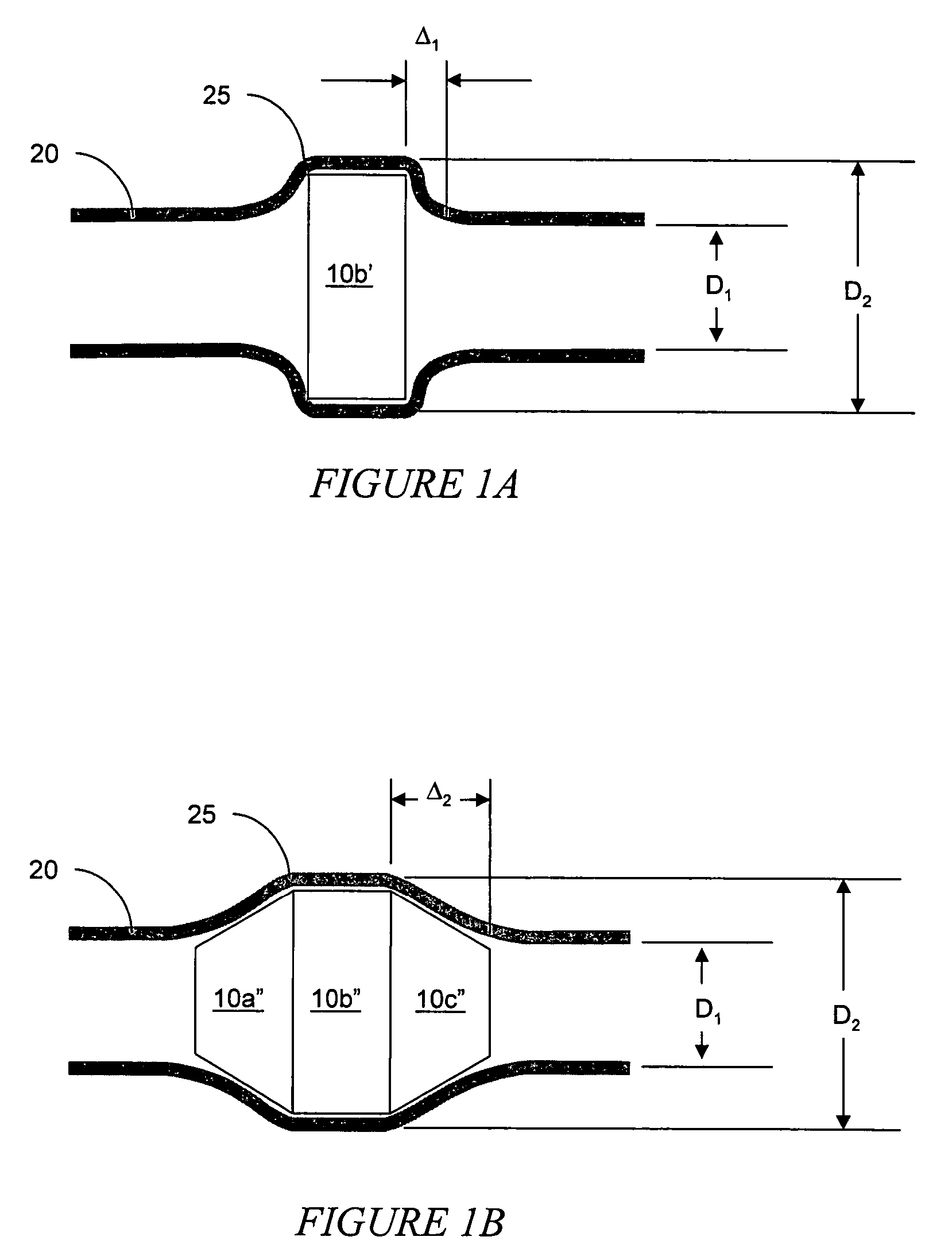
[0034]A cross-section of a natural bodily lumen 20 including an anchor 10b′ is illustrated in FIG. 1A. Generally, the lumen defines a natural diameter, D1, that may vary over time. The anchor provides a radially-outward securing force directed against the luminal walls. Depending upon the structure of the anchor 10b′ and the compliance of t...


PUM


Abstract

The present invention relates to methods and articles for anchoring within a natural bodily lumen. An anchor is adapted to provide differing radially-outward forces along its length, a securing force and a transitional force. Production of these forces can be controlled by varying a physical property of the anchor, such as its stiffness, thickness, or shape. For example, the stiffness of an elongated anchor can be varied from a relatively soft value at its proximal and distal ends to a relatively stiff value at its center by varying the diameter of wire forming the anchor, thereby tailoring it to an intended application. Such force tailoring can be combined with external barbs and used to reliably anchor other instruments, such as feeding tubes and intestinal sleeves.

Description

RELATED APPLICATION[0001]This application claims the benefit of U.S. Provisional Application No. 60 / 611,038, filed on Sep. 17, 2004. The entire teachings of the above application are incorporated herein by reference.BACKGROUND OF THE INVENTION[0002]Anchors are used in the treatment of patients to secure devices at a desired location within a natural bodily lumen. For example, anchors can be used to secure tubes within the digestive tract, such as intestinal sleeves. For example intestinal sleeves anchored within the gastrointestinal tract are described in U.S. application Ser. No. 10 / 339,786 filed on Jan. 9, 2003, claiming priority to U.S. Provisional Application No. 60 / 430,321 filed on Dec. 2, 2002; Ser. No. 10 / 858,852 filed on Jun. 16, 2004, claiming priority to U.S. Provisional Application Nos. 60 / 528,084 filed on Dec. 9, 2003 and 60 / 544,527 filed on Dec. 14, 2004, incorporated herein by reference in their entirety.SUMMARY OF THE INVENTION[0003]This invention is generally related...

Claims


Application Information

Patent Timeline
Patent Type & Authority Patents(United States)
IPC IPC(8): A61M5/00A61F2/04A61F2/06A61F2/82A61F2/86A61F2/90
CPCA61F2/04A61F2/07A61F2/82A61F2/86A61F5/0076A61F2/06A61F2/90A61F2/91A61F2002/045A61F2002/828A61F2002/8483A61F2250/0036A61F2250/0037A61F2/89A61F2/915A61F2002/072A61F2002/075A61F2002/9534A61F2210/0076A61F2220/0016A61F2220/005A61F2220/0058A61F2220/0066A61F2220/0075
Inventor LEVINE, ANDY H.MEADE, JOHN C.MELANSON, DAVID A.
Owner GI DYNAMICS
Why Eureka
Try Eureka