
Multi cyclone collector

a multi-cyclone collector and collector technology, applied in the direction of filtration separation, cleaning filter means, separation processes, etc., can solve the problems of space waste, limited size of the conventional multi-cyclone collector mentioned above, etc., and achieve the effect of improving arrangement structure and increasing collecting efficiency

Inactive Publication Date: 2010-10-19
LG ELECTRONICS INC
View PDF16 Cites 13 Cited by
  • Summary
  • Abstract
  • Description
  • Claims
  • Application Information

AI Technical Summary

Benefits of technology

The present invention is a multi cyclone collector that solves problems in the related art by improving the arrangement structure of each second cyclone collector to increase the number of collectors. The collector includes a first cyclone collector for drawing in outside air and collecting dust, a second cyclone collector for collecting minute dust, a collecting container for collecting minute dust separated from air by the second cyclone collector, and a case for accommodating the first and second cyclone collectors. The arrangement structure of each second cyclone collector is improved to increase collecting efficiency. The collecting container is formed in a polygonal shape with at least two edges to increase the collecting space. Overall, the invention improves the efficiency of collecting dust from air.

Problems solved by technology

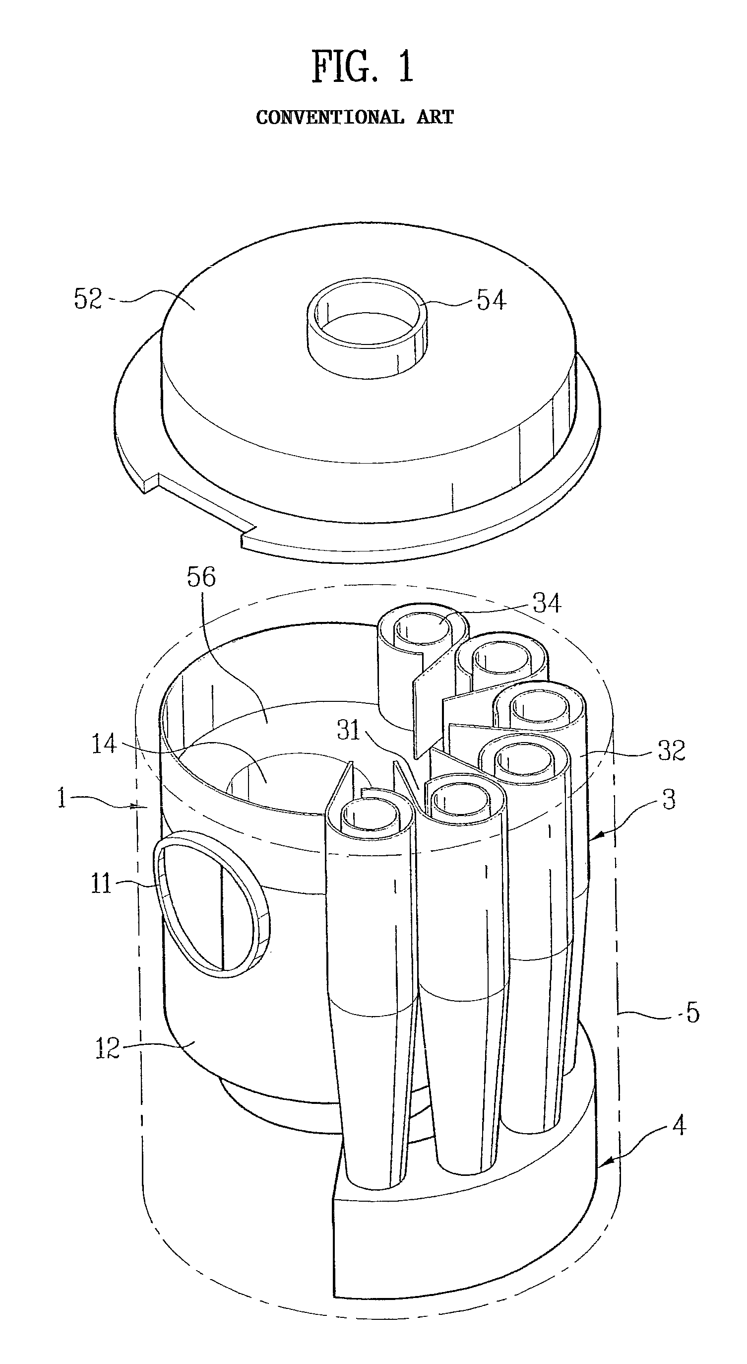
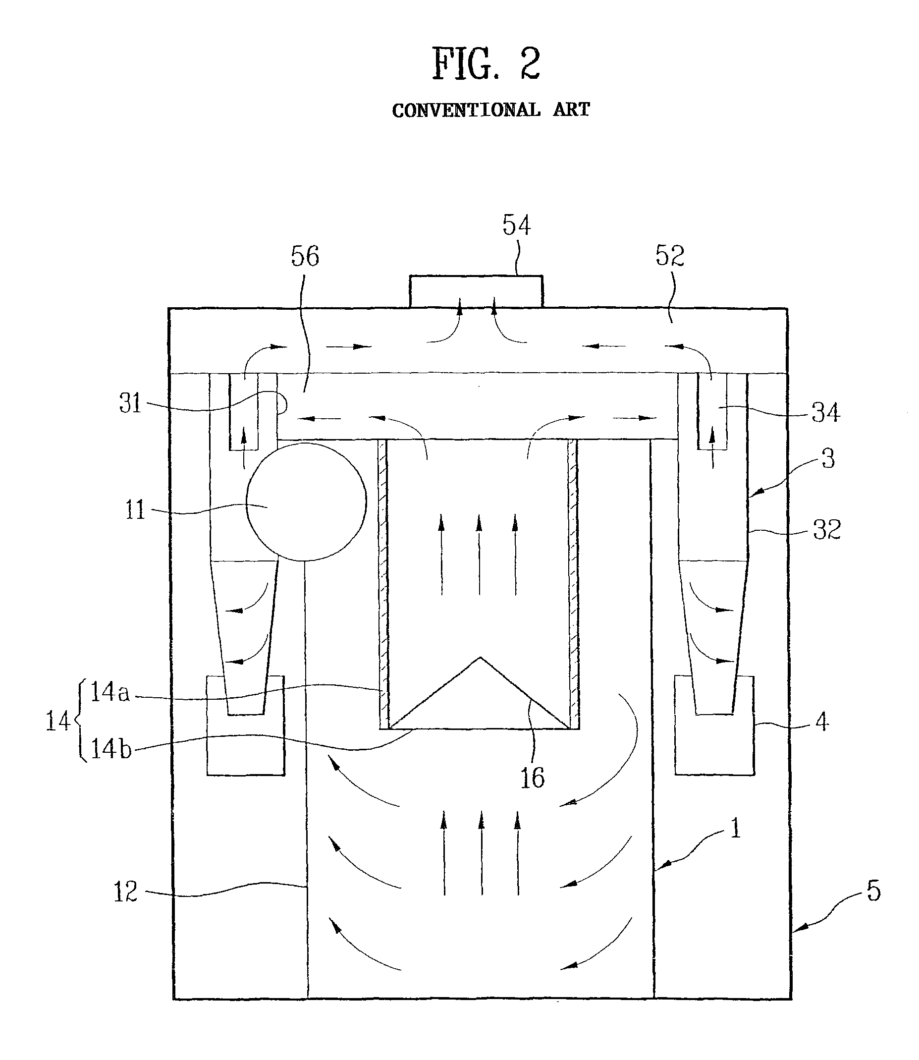
A total size of the conventional multi cyclone collector mentioned above is however limited because a space for installing the multi cyclone collector is limited in a vacuum cleaner.
In this regard, the edge portion in the case 5 exists only as an empty space, thereby raising a problem of space waste.

Method used


Image

  • Multi cyclone collector
  • Multi cyclone collector
  • Multi cyclone collector

Examples


Embodiment Construction

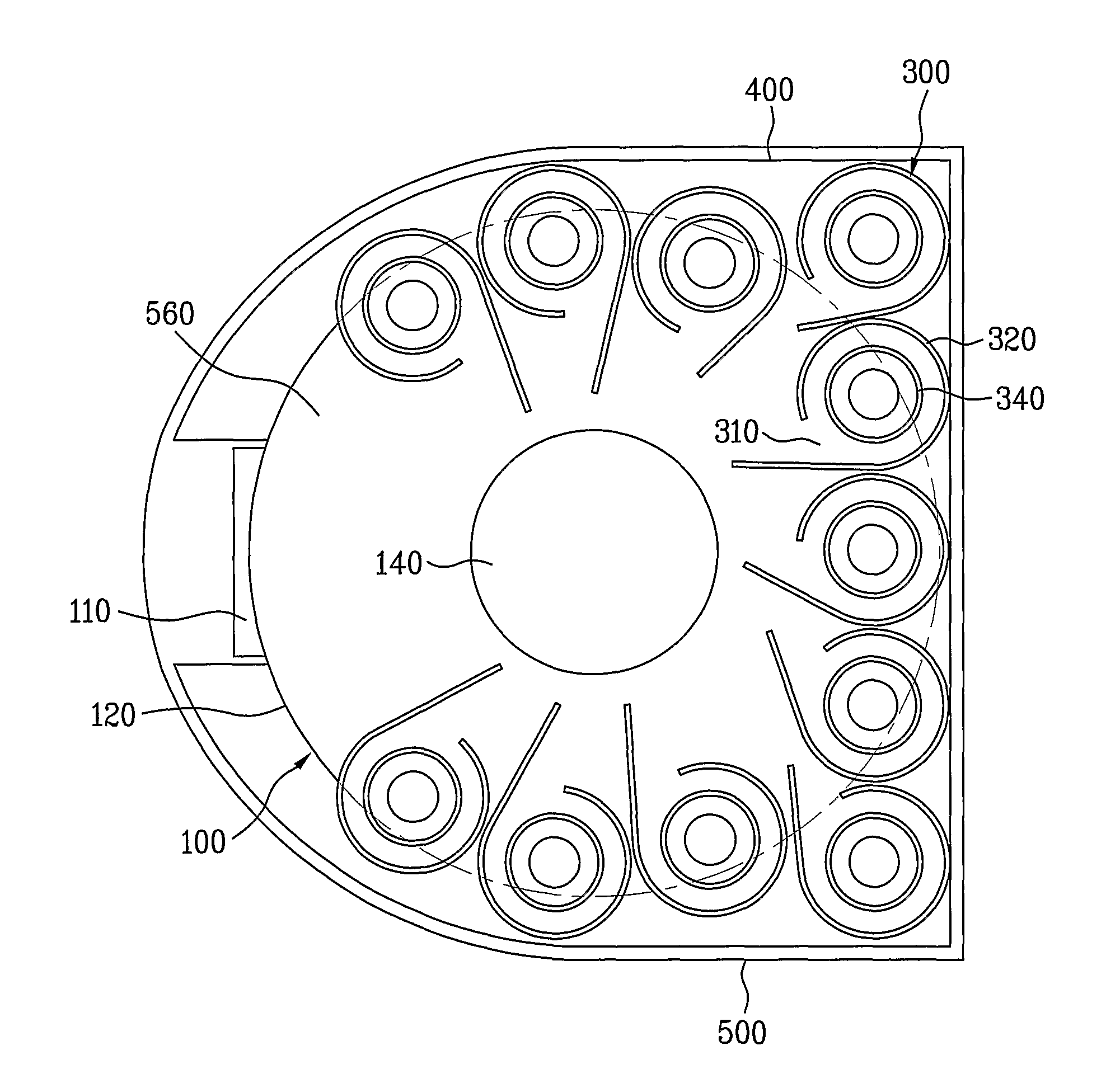
[0032]Hereinafter, each embodiment of the present invention will be described with reference to appended drawings as follows. First, FIGS. 3 and 4 illustrate a multi cyclone collector in accordance with an embodiment of the present invention. In other words, the multi cyclone collector in accordance with the embodiment of the present invention includes a first cyclone collector 100, a plurality of second cyclone collectors 300, a collecting container 400, and a case 500.

[0033]The first cyclone collector 100 is configured to suck up outside air, to separate dust from the outside air firstly, and to collect the dust.

[0034]The plurality of second cyclone collectors 300 is configured to separate minute dust from air secondly, the air from which dust are separated by the first cyclone collector 100 firstly, and then to collect the separated dust. The plurality of second cyclone collectors 300 is provided at a circumference of the first cyclone collector 100.

[0035]The collecting container...


PUM

PropertyMeasurementUnit
distanceaaaaaaaaaa
semi-circular shapeaaaaaaaaaa
shapeaaaaaaaaaa

Abstract

A multi cyclone collector with an improved structure is disclosed for providing the highest number of second cyclone collector (300) by disposing a plurality of second cyclone collector (300) in a non circular shape (400) arrangement along a first cyclone collector, thereby increasing collecting efficiency.

Description

TECHNICAL FIELD[0001]The present invention relates to a multi cyclone collector, and more particularly, to, of a first cyclone collector for separating dust firstly and a plurality of second cyclone collectors for separating the dust secondly, an arrangement of the plurality of second cyclone collectors.BACKGROUND ART[0002]In general, a cyclone collector is a device for collecting dust particle (hereinafter, referred to as “dust”) contained in air using a cyclone principle, and normally applied to a vacuum cleaner.[0003]Recently, a multi cyclone collector having a plurality of cyclone collectors connected thereto is used for increasing collecting efficiency. An example of the multi cyclone collector is in a Japanese laid open utility model NO. S52-14775.[0004]Referring to FIGS. 1 and 2, a conventional multi cyclone collector will be described. The multi cyclone collector includes a cyclone (hereinafter, referred to as “a first cyclone collector 1”) for collecting dust being relative...

Claims


Application Information

Patent Timeline
Patent Type & Authority Patents(United States)
IPC IPC(8): B01D45/00
CPCA47L9/1625A47L9/1641B01D45/16B04C5/24Y10S55/03A47L9/16
Inventor HYUN, KIE TAKSON, YOUNG BOKCHO, HYOUNG JOOJEONG, KYEONG SEON
Owner LG ELECTRONICS INC
Learn More