Power applicator system for conveyor belt fasteners

a technology of conveyor belts and applicators, which is applied in the direction of nail dispensers, paper/cardboard containers, manufacturing tools, etc., can solve the problems of insufficient support of the drive rod, the inconvenient use of guide blocks of elastomeric materials primarily used in manual hammer drive applications,

Active Publication Date: 2010-10-26
FLEXIBLE STEEL LACING
View PDF13 Cites 17 Cited by
  • Summary
  • Abstract
  • Description
  • Claims
  • Application Information

AI Technical Summary

Benefits of technology

[0010]In yet another aspect, the power tool is adapted for generating high impact forces, e.g., 50,000 lbs., against rivets in the guide block bores so that generally only two or three tool firings are needed to properly drive and set one of the rivets for attaching the belt fastener to a belt end. To allow for such high impact forces to be employed, the power applicator system limits the amount or distance the drive rod of the tool projects beyond the lower surface of the guide block after completion of its drive stroke. It has been found that by limiting this distance to preferably about 0.100 inch, with some excess travel provided by a resilient stop of the tool drive rod assembly, that the desired high force tool can be employed while minimizing instances of rivet breakage and limiting the dishing of the upper plate of the fastener accordingly during fastener installation operations.

Problems solved by technology

Prior guide blocks of elastomeric material primarily used in manual hammer drive applications would not be useful in the present direct drive power system as the elastomeric material would not provide sufficient support to the drive rod to minimize drive rod bending and instances of breakage thereof and to ensure consistent and reliable rivet setting therewith.

Method used


Image

  • Power applicator system for conveyor belt fasteners
  • Power applicator system for conveyor belt fasteners
  • Power applicator system for conveyor belt fasteners

Examples


Embodiment Construction

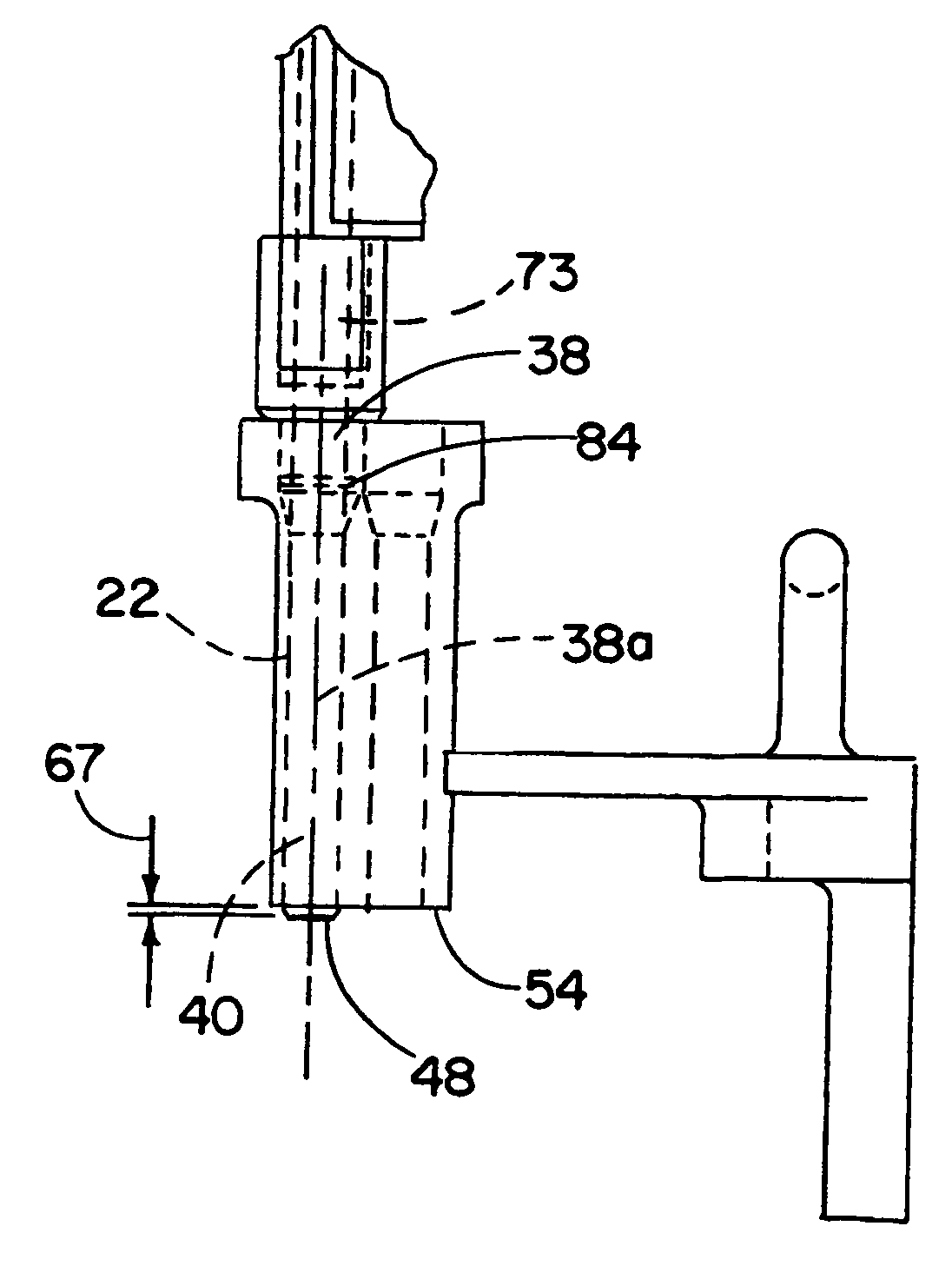
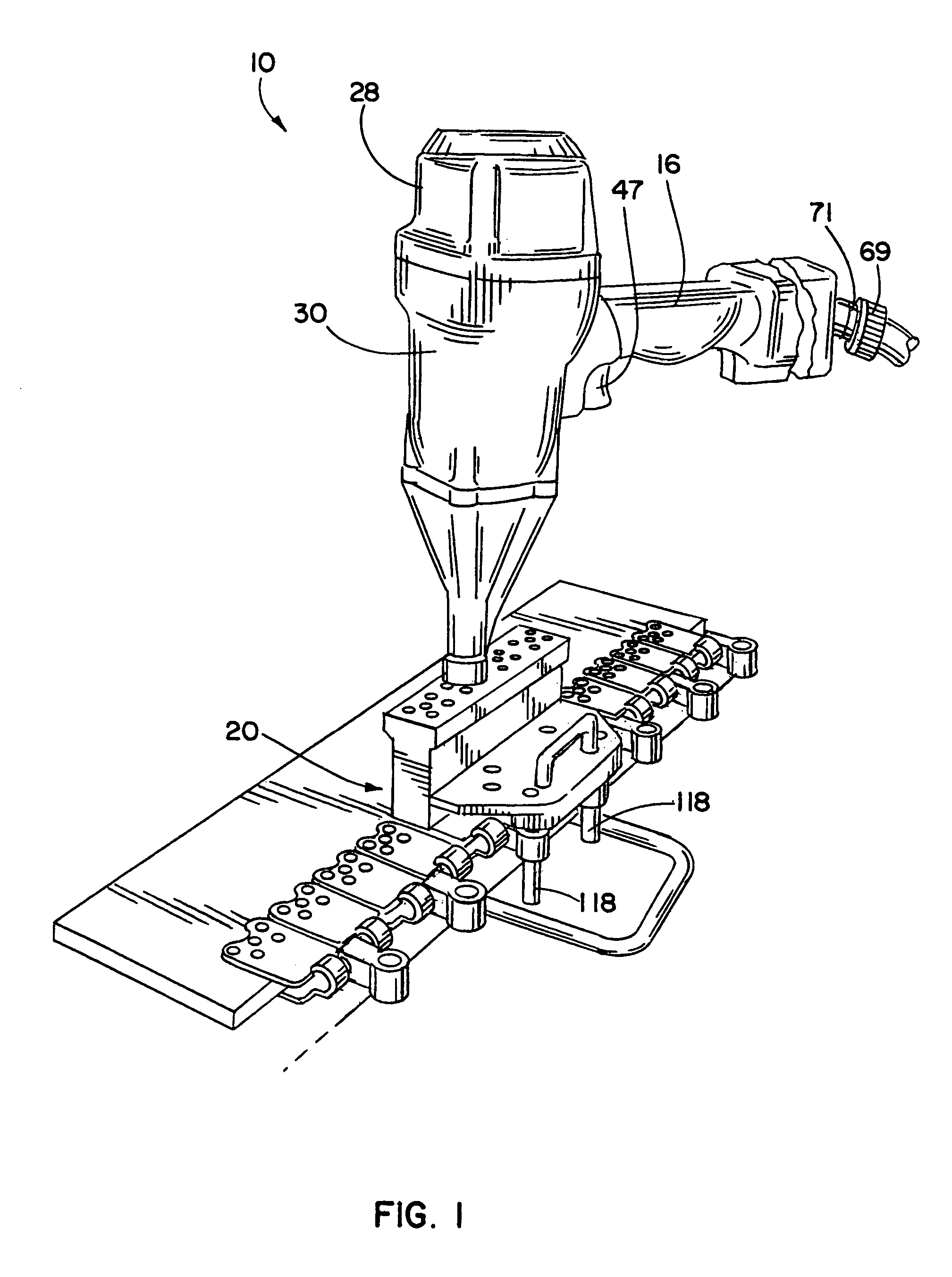
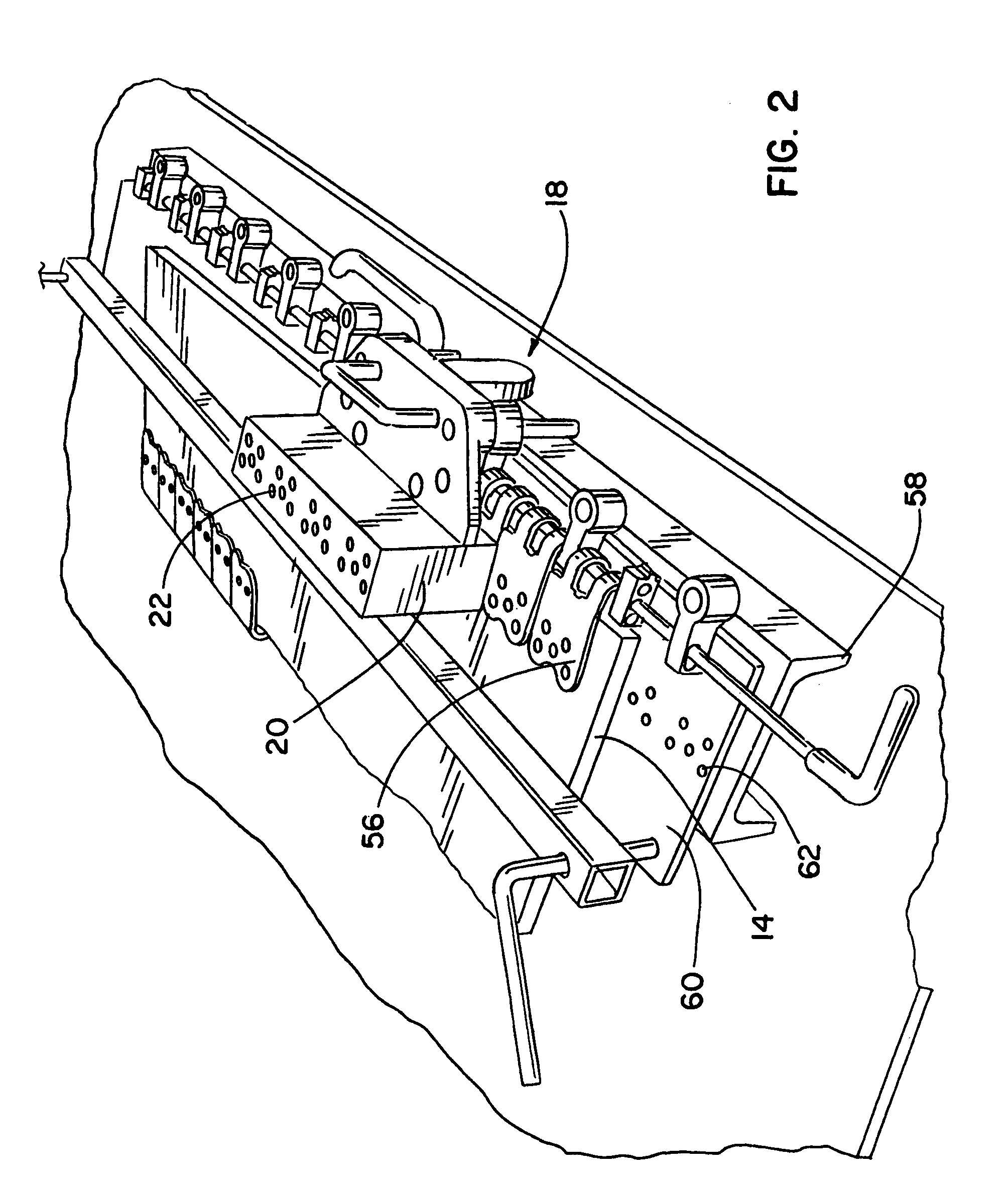
[0025]In FIGS. 1-5, a power applicator system 10 for attaching conveyor belt fasteners 12 to belt ends 14 is shown. The system 10 includes a power tool apparatus 16 and a guiding apparatus 18 that together cooperate in providing for ease of attachment of the belt fasteners 12 to the belt ends 14. The guiding apparatus 18 includes a guide block 20 having through bores 22 in which attachment members 24 (FIGS. 15 and 16) for the belt fasteners 12 are loaded. As shown, the attachment members 24 are preferably rivets, although other attachment members are also contemplated, e.g., nails or staples. In addition, the illustrated rivets 24 also include pilot nails 26 that are separably attached thereto, as is known. Accordingly, the term rivets herein are also meant to encompass rivets having separably attached pilot nails.

[0026]The power tool apparatus 16 herein includes a power tool or gun 28 that has a relatively compact lightweight body 30 as the tool 28 does not carry a strip of rivets ...


PUM

PropertyMeasurementUnit
distanceaaaaaaaaaa
diameteraaaaaaaaaa
diameteraaaaaaaaaa

Abstract

A system for applying belt fasteners to belt ends is disclosed. The system includes a power tool apparatus and a guiding apparatus. The guide apparatus includes a guide block having guide bores in which attachment members, e.g., rivets, are held in position relative to the belt fasteners so that a drive rod of the power tool impacts the rivets in the guide block bores. The guide block preferably is of a hard material, e.g. a machined steel or powder steel, for proper guiding of the drive rod and rivet during riveting operations.

Description

CROSS-REFERENCE TO RELATED APPLICATION[0001]This application is based upon and claims the benefit under 35 U.S.C. §119 of prior provisional application No. 60 / 577,988, filed Jun. 8, 2004, which is hereby incorporated herein by reference in its entirety.FIELD OF THE INVENTION[0002]The invention is to an applicator system for attaching conveyor belt fasteners to belt ends and, more particularly, to an applicator system using a power tool for attaching belt fasteners to belt ends.BACKGROUND OF THE INVENTION[0003]Prior applicator systems are known for attaching rivet conveyor belt fasteners to belt ends either by using manual force as by hammer blows or with a power applicator, see U.S. Pat. No. 5,487,217 to Richardson et al. The '217 patent is addressed to the perceived need to provide easier installation of the rivet belt fasteners over that afforded by prior manual systems. Accordingly, the system of the '217 patent utilizes a non-manually powered rivet driving tool.[0004]However, th...

Claims


Application Information

Patent Timeline
Patent Type & Authority Patents(United States)
IPC IPC(8): B23P11/00B25C5/06F16G3/16
CPCF16G3/16Y10T29/5343Y10T29/53713Y10T29/53478Y10T29/5118Y10T29/49954Y10T29/53513Y10T29/49998Y10T29/5377
Inventor DANIELS, WILLIAM JAMESVOGRIG, JOSEPHWESTPHALL, GREGORYWINKELMAN, JOHN H.
Owner FLEXIBLE STEEL LACING
Why Eureka
Try Eureka