Electrosurgical radio frequency energy transmission medium

a radio frequency energy and transmission medium technology, applied in the field of electrosurgical system and method, can solve the problems of reducing treatment energy, affecting the operation of other electronic equipment in the surgical arena, etc., and achieves the effect of reducing electrical field, minimizing stray rf energy radiated, and maximizing application of rf energy

Inactive Publication Date: 2010-10-26
COVIDIEN AG
View PDF23 Cites 18 Cited by
  • Summary
  • Abstract
  • Description
  • Claims
  • Application Information

AI Technical Summary

Benefits of technology

[0007]The present disclosure relates to transmission of electrosurgical radio frequency (“RF”) energy. An electrosurgical cable is disclosed having close proximity electrical field coupling between a supply and return transmission lines. The coupling maximizes application of the RF energy delivered during surgery and minimizes the stray RF energy radiated by the supply and return leads. Close proximity electrical field coupling significantly reduces the electrical field via field cancellation thereby increasing patient and surgeon safety. Coupling provides a low loss inductive / capacitive (“LC”) transmission medium via a three-dimensional geometric orientation of the supply and return leads. The geometric orientation affects LC reactive components and reduces uncontrolled capacitive reactance caused by stray RF radiation. In particular, capacitive reactance is caused by antenna effect (e.g., rapid discharge of stray RF energy) for transmission mediums shorter than half a wavelength. Therefore, loss of stray RF energy is contained to a predetermined level which also reduces capacitive loading to the energy source (e.g., electrosurgical energy).

Problems solved by technology

During transmission an electrical field is generated through the cable and stray electrosurgical RF energy is typically emitted along the cable path, which tends to reduce treatment energy.
Moreover, the electrical fields may interfere with the operation of other electronic equipment in the surgical arena, such as patient monitoring equipment.

Method used


Image

  • Electrosurgical radio frequency energy transmission medium
  • Electrosurgical radio frequency energy transmission medium
  • Electrosurgical radio frequency energy transmission medium

Examples


Embodiment Construction

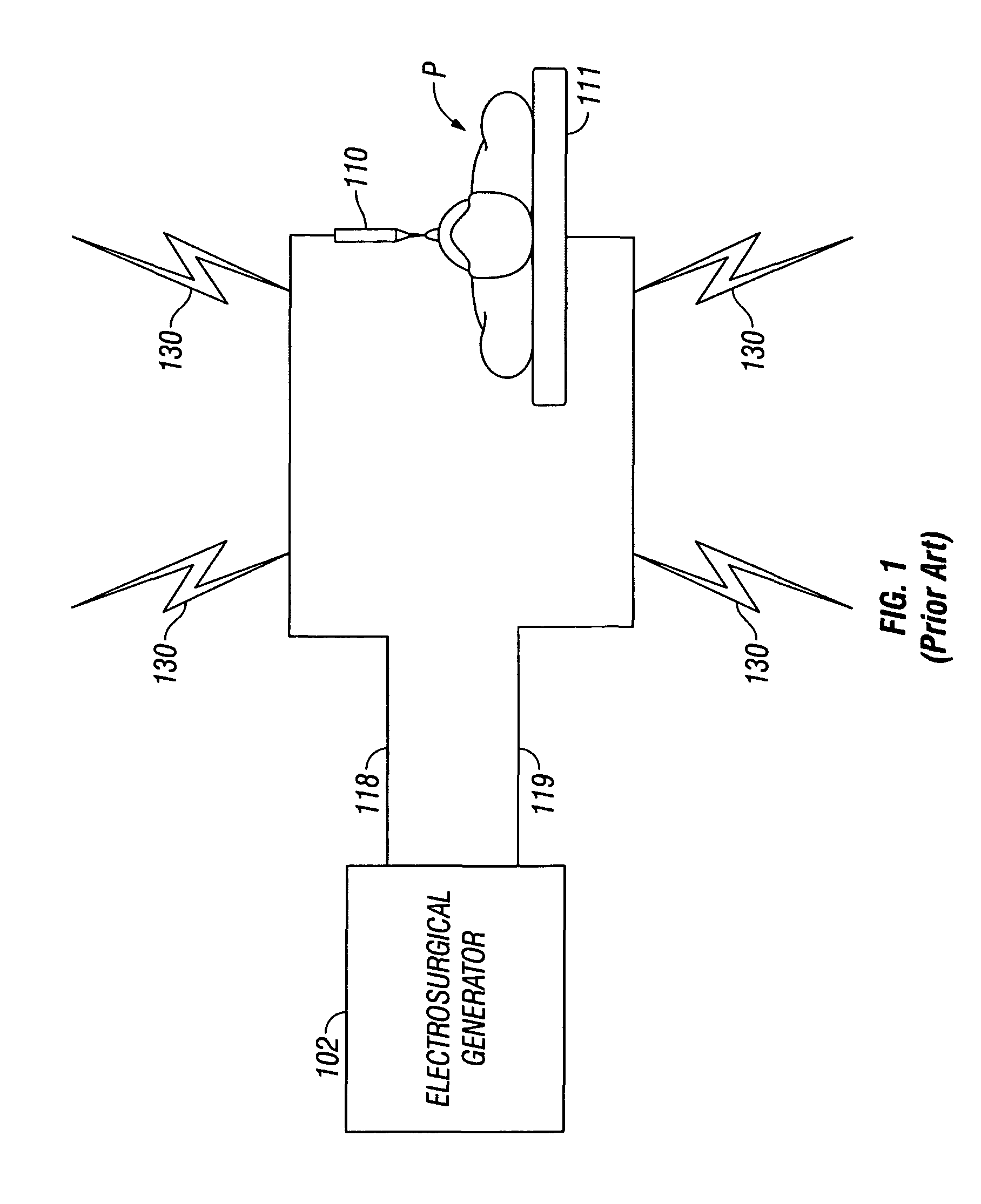
[0018]Particular embodiments of the present disclosure are described hereinbelow with reference to the accompanying drawings. In the following description, well-known functions or constructions are not described in detail to avoid obscuring the present disclosure in unnecessary detail. Those skilled in the art will understand that the invention according to the present disclosure may be adapted for use with either monopolar or bipolar electrosurgical systems and either an endoscopic instrument or an open instrument. It should also be appreciated that different electrical and mechanical connections and other considerations apply to each particular type of instrument.

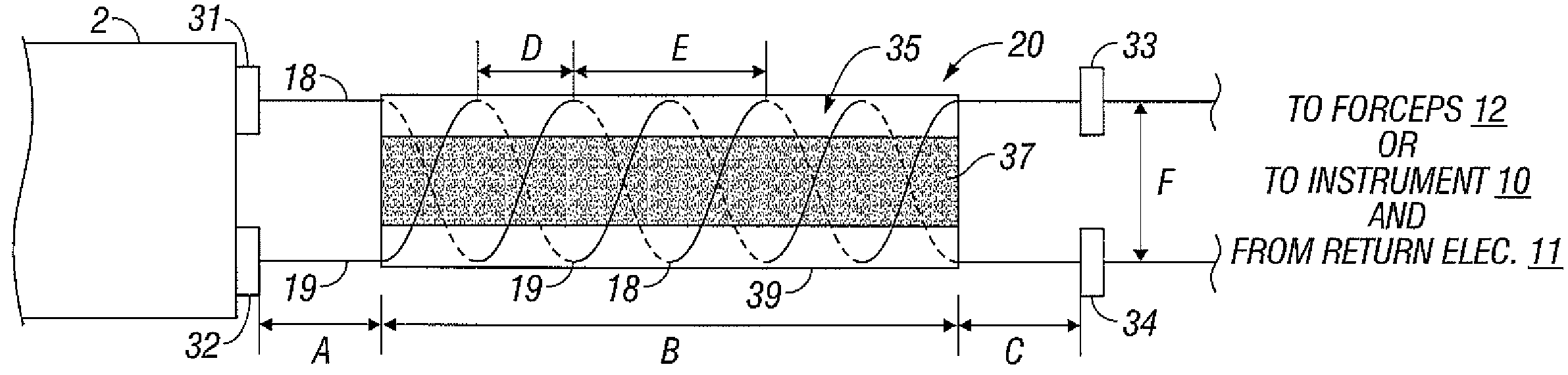
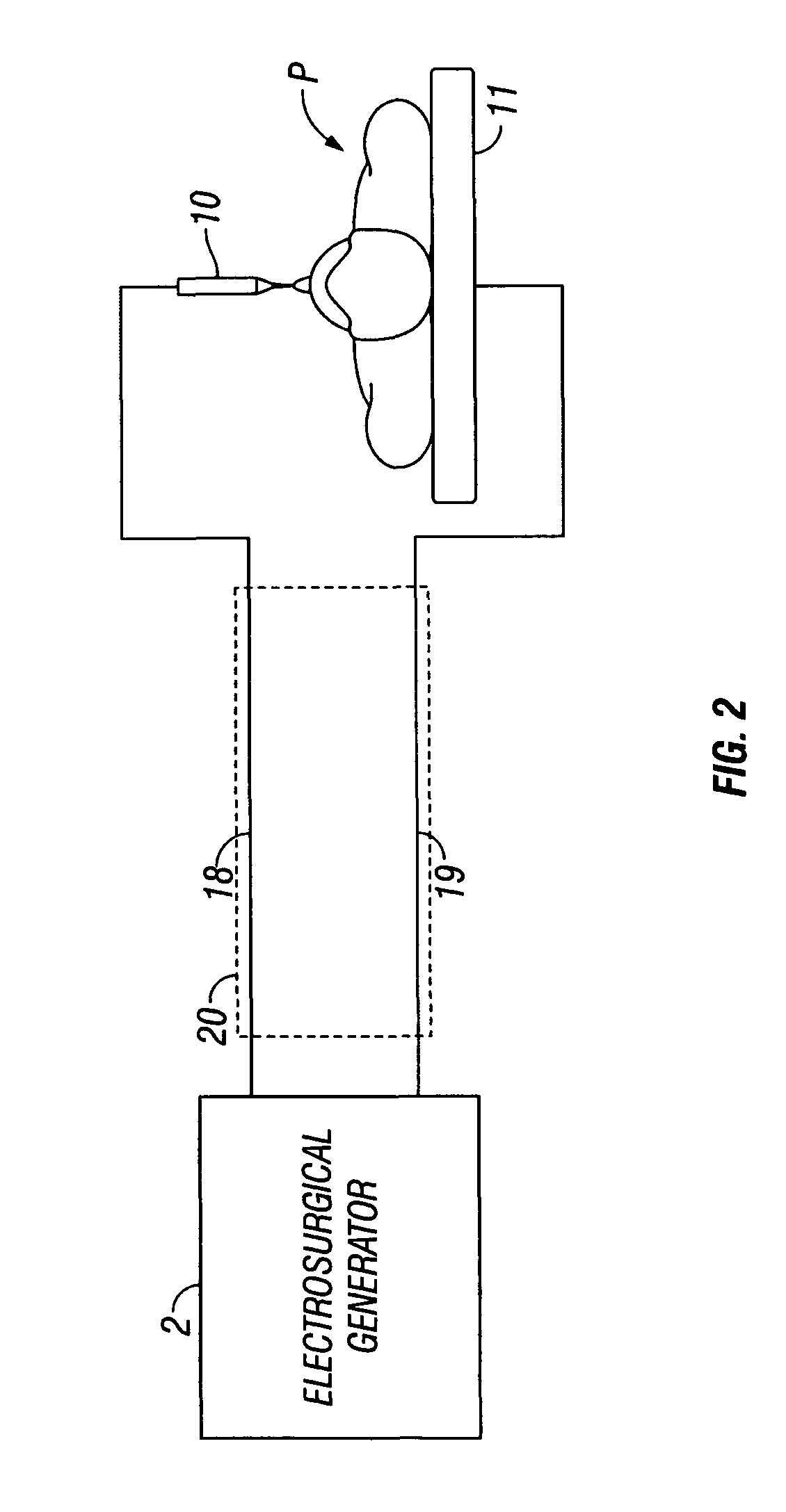
[0019]The present disclosure provides for an electrosurgical transmission cable wound in a double helix having a proximal geometric relationship in three-dimensional physical space, to control the inductive and capacitive components of the transmission cable and significantly reduce the capacitive leakage due to RF radiat...


PUM


Abstract

A system and method for transmitting electrosurgical energy from a generator to an electrosurgical instrument are provided. The electrosurgical system includes a generator adapted to generate electrosurgical energy for treating tissue. The generator includes one or more active output terminals which supply energy to the tissue. The active output terminals are operatively connected to one or more supply lines. The generator also includes one or more return output terminal which returns energy from the tissue. The return output terminals are operatively connected to at least one return line. The system also includes an electrosurgical instrument operatively connected to the one or more supply lines and one or more return electrodes operatively connected to one or more return lines. The system further includes an electrosurgical cable including one or more supply lines and one or more return lines. The one or more supply lines and one or more return lines are wound in a double helix fashion such that the electrical field along the cable is mitigated along the length thereof.

Description

BACKGROUND[0001]1. Technical Field[0002]The present disclosure relates to an electrosurgical system and method for performing electrosurgical procedures. More particularly, the present disclosure relates to a system and method for effectively transmitting electrosurgical radio frequency energy from an electrosurgical generator to a treatment site with reduced energy loss.[0003]2. Background of Related Art[0004]Electrosurgery involves application of high radio frequency electrical current to a surgical site to cut, ablate, or coagulate tissue. In monopolar electrosurgery, a source or active electrode delivers radio frequency energy from the electrosurgical generator to the tissue and a return electrode carries the current back to the generator. In monopolar electrosurgery, the source electrode is typically part of the surgical instrument held by the surgeon and applied to the tissue to be treated. A patient return electrode is placed remotely from the active electrode to carry the cu...

Claims


Application Information

Patent Timeline
Patent Type & Authority Patents(United States)
IPC IPC(8): A61B18/04
CPCA61B18/14A61B18/00A61B18/1445A61B2018/00178A61B2018/00345A61B2018/00404A61B2018/00589A61B2018/00619A61B2018/00702A61B2018/00791A61B2018/00827A61B2018/00875A61B2018/00892
Inventor ORSZULAK, JAMES H.
Owner COVIDIEN AG
Why Eureka
Try Eureka