Axial gap type motor

a gap type, axial gap technology, applied in the direction of mechanical equipment, superconductor devices, magnetic circuit shape/form/construction, etc., can solve the problems of high precision, bottleneck in manufacture, and difficulty in providing a predetermined air gap, so as to achieve high output and further miniaturization

Inactive Publication Date: 2010-10-26
SUMITOMO ELECTRIC IND LTD +1
View PDF26 Cites 18 Cited by
  • Summary
  • Abstract
  • Description
  • Claims
  • Application Information

AI Technical Summary

Benefits of technology

[0053]As apparent from the above description, according to the invention, the armature coils have an empty core, or a core member composed of a flux collector. Therefore, the armature coils disposed in the stators and the rotary field bodies disposed in the rotors can be arrange close to each other, high output can be obtained, and miniaturization of the motor can be achieved.
[0054]Particularly if the rotary field bodies and / or the armature coils are formed from a superconductive material, high output can be achieved while further miniaturization can be attained.
[0055]Further, if the stators and the rotors are alternately disposed with the rotary shaft as a main shaft, and the stators at both axial ends are fixed to the back yokes, the stators and the rotors can be disposed in high density, leakage of a magnetic field the magnetic-flux directions of which is the axial direction to the outside can be shielded, and the magnetic field can be strengthened, thereby realizing high output of torque. Moreover, the stators and the rotors can also be simply disassembled by removing the stators at both axial ends from the back yokes.
[0056]Further, if stators are connected together with predetermined spacing by a connecting spacer, and rotors are inserted into air gaps between the stators, the gap between a rotor and a stator can be specified to a predetermined dimension with precision, and a number of rotors and stators can be assembled simply.
[0057]As such, from the points that high output can be obtained while miniaturization can be achieved, assembling or disassembling is easy, and maintainability is excellent, a series coupling synchronous motor optimal as a motor for propulsion of large ships, such as government and public office ships or passenger ships.

Problems solved by technology

Therefore, in a series coupling synchronous axial gap type motor in which rotors and stators are alternately disposed with required air gaps in an axial direction, it is difficult to provide a predetermined air gap between a rotor and a stator to arrange them with high precision, which becomes a bottleneck in manufacture.
As a result, it takes time and effort to provide a required air gap between the rotor and the stator.
Further, an operator's finger has the danger of being caught in between the permanent magnets and the iron core.
Therefore, high output will be hardly obtained, and the motor itself will be made large in the axial direction of the rotary shaft.

Method used


Image

  • Axial gap type motor
  • Axial gap type motor
  • Axial gap type motor

Examples


first embodiment

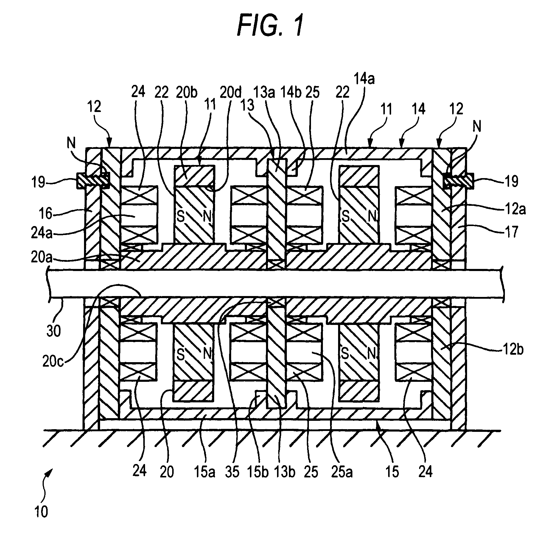
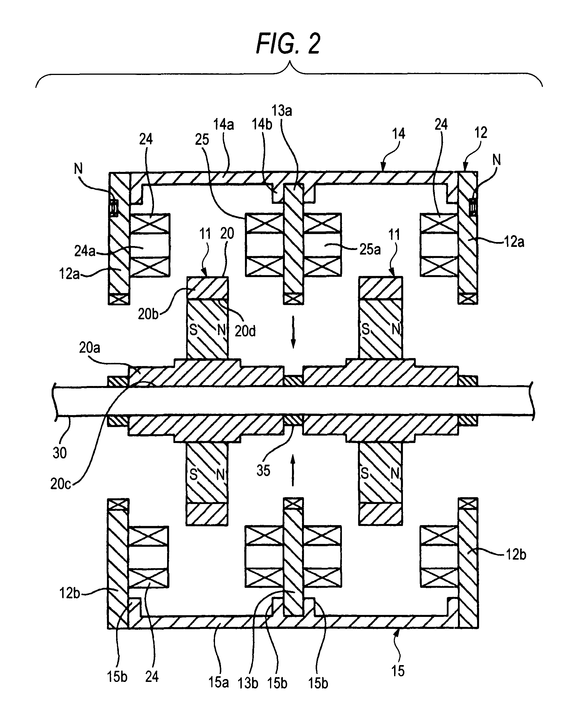
[0088]FIGS. 1 to 3 show a series coupling synchronous axial gap type motor 10 of the invention. In addition, FIGS. 1 and 2 show a configuration in which two rotors 11, stators 12 at both axial ends, and an intermediate stator 13 are alternately disposed in the axial direction of a rotary shaft 30 in order to simplify illustration. However, as shown in FIG. 3, a number of intermediate stators 13 are provided, and rotors 11 are disposed between adjacent stators 12 and 13 and between adjacent stators 13 and 13, respectively.

[0089]A rotor 11 is fixed to the rotary shaft 30, and stators 13 and 12 are disposed with required air gaps on both sides of the rotor 11 in its axial direction. The stators 12 and 13 are connected to each other by upper and lower connecting spacers 14 and 15, and the stators 12 at both axial ends are fixed to back yokes 16 and 17 with screws 19.

[0090]The rotor 11 has a disk-like rotor part 20b which is made to project in the vertical direction in the drawing from t...

second embodiment

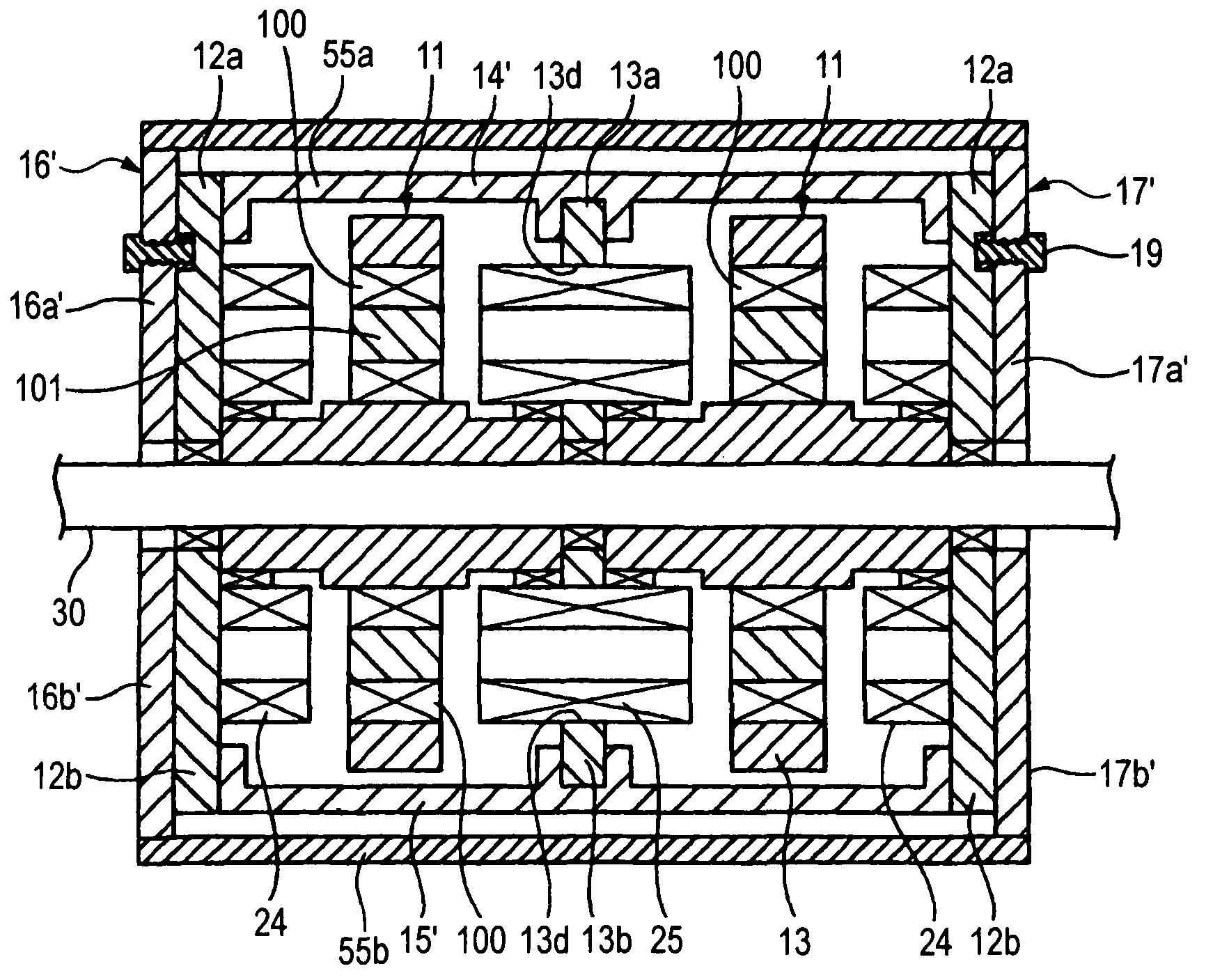
[0116]FIG. 7 shows a

[0117]In the second embodiment, a through-hole 13d is provided in a stator 13 in an intermediate position to which armature coils 25 are attached, the armature coils 25 are fitted into and fixed to the through-hole 13d, and both ends of the armature coils are made to project from both end faces of the stator 13, and are made to face field coils 100 made of a superconductive material with a predetermined air gap therefrom.

[0118]The armature coils 25 and the stators 12 at both ends form empty cores, flux collectors 101 as core members are disposed in hollow parts of the field coils 100, and these flux collectors 101 are in almost the same positions as the tips of the field coils 100. In addition, the flux collectors may be made to project a little.

[0119]Further, back yokes 16′ and 17′ at right and left both ends are also split into upper and lower pieces, respectively, so as to provide upper back yokes 16a′ and 17a′ and lower back yokes 16b′ and 17b′. The upper bac...

third embodiment

[0127]In the third embodiment, it is necessary to cool the field coils 100 made of a superconductive material to an ultra-low temperature. Thus, liquid hydrogen stored in a liquid hydrogen tank 60 is introduced into a hollow part 30a of the rotary shaft 30 to cool a bulk magnet 22′.

[0128]Specifically, the hollow part 30a opened towards one end in the axial direction is provided in the rotary shaft 30, and a pipe 63 having a refrigerant passage 62 is inserted into the hollow part 30a via a bearing 64 from the liquid hydrogen tank 60, and is terminated immediately before a position where a rotor is disposed. The pipe 63 is made into a double-tube structure, the refrigerant passage 62 which allows liquid hydrogen pass therethrough is provided in a central space, and liquid hydrogen is filled into the hollow part 30a in the position where a rotor is disposed, thereby cooling the magnetic coils 100. Meanwhile, the outer peripheral space of the pipe 62 is made into a vacuum insulation spa...


PUM


Abstract

A series coupling synchronous axial gap type motor where rotors and stators are alternately stacked with required air gaps in the axial direction of a rotary shaft as a main shaft, is provided. The rotors are fixed to the rotary shaft, and the stators are disposed such that they cannot be interlocked with the rotary shaft. A plurality of rotary field bodies are attached to each of the rotor around the axis, and a plurality of armature coils are made to face the rotary field bodies with an air gap therefrom and are attached to each of the stators around the axis such that their magnetic-flux directions are directed toward the axial direction. The armature coils have an empty core, or a core member composed of a magnetic body attached thereto.

Description

TECHNICAL FIELD[0001]The present invention relates to an axial gap type motor, and specifically, to a series coupling synchronous high-output motor suitably used as driving sources of vehicles, ships, etc., particularly as motors for propulsion of large ships, such as government and public office ships or passenger ships.RELATED ART[0002]Conventionally, there are a radial gap type motor and an axial gap type motors as motors. As the radial gap type motor, a motor in which a rotor is provided in a hollow part of a stator having an annular cross-section such that the magnetic-flux directions of coils is directed to a radial direction is widely and generally used. Meanwhile, the axial gap type motor, as disclosed in Japanese Unexamined Patent Application Publication No. 2004-140937, is configured such that stators are disposed to face each other in the axial direction of a rotor, and the magnetic-flux directions of coils are directed to the axial direction.[0003]In the conventional axi...

Claims


Application Information

Patent Timeline
Patent Type & Authority Patents(United States)
IPC IPC(8): H02K21/24H02K1/18H02K55/02
CPCH02K21/24H02K55/04Y02E40/625Y02E40/60
Inventor OKAZAKI, TORUOHASHI, SHINGOSUGITOMO, HIDEHIKOTAKEDA, TOSHIO
Owner SUMITOMO ELECTRIC IND LTD
Why Eureka
Try Eureka