
Voltage regulator with pass transistors carrying different ratios of the total load current and method of operation therefor

a voltage regulator and transistor technology, applied in the direction of ac network voltage adjustment, ac network circuit arrangement, instruments, etc., can solve the problems of poor transient performance of the voltage regulator, no voltage regulator currently available on the market, and no current voltage regulator that provides an efficient, high-efficiency

Active Publication Date: 2010-10-26
NXP USA INC
View PDF5 Cites 19 Cited by
  • Summary
  • Abstract
  • Description
  • Claims
  • Application Information

AI Technical Summary

Benefits of technology

The present invention provides a voltage regulator circuit, an integrated circuit, and a method for providing a regulated voltage. This helps to ensure that the voltage provided is stable and reliable, which can be useful in various applications where a stable voltage is needed.

Problems solved by technology

In the field of voltage regulators, there is no voltage regulator currently available on the market that provides an efficient, high-performance voltage regulation over a wide range of possible loads, whilst maintaining an ultra-low bias current that ensures minimum current consumption in standby mode (i.e. when there is no load).
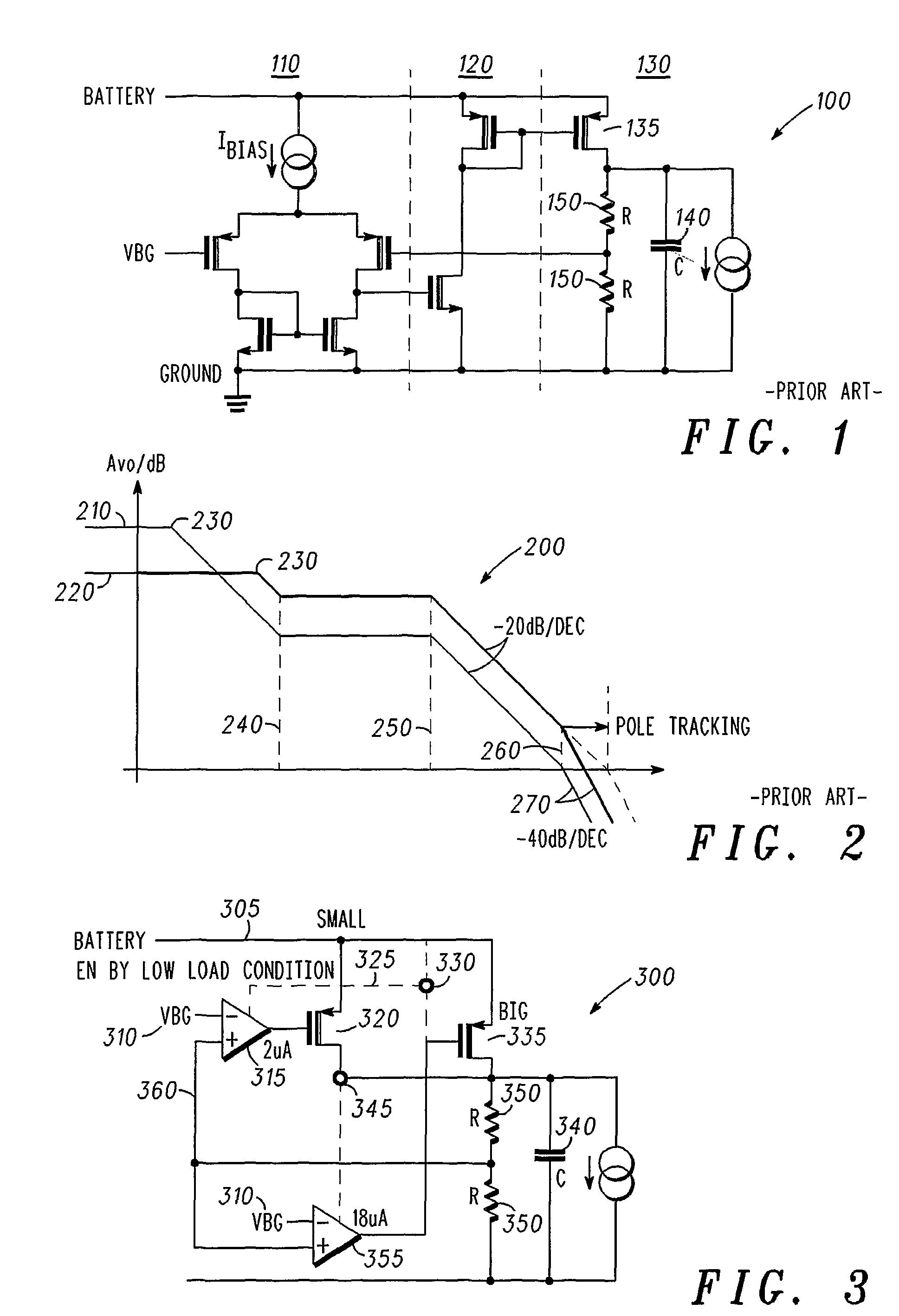
Thus, the regulator performance suffers from either:(i) The transient performance of the voltage regulator is poor, if it is operating at a relatively low current (Icc) for all loads; or(ii) The regulator is likely operating inefficiently, if the voltage regulator is operating with a relatively high current (Icc) for all possible loads.
Thus, as can be readily appreciated, increasing the load results in the following circuit changes:(i) The Pole increases faster;(ii) The Gain decreases 270; and(iii) There is more remaining gain at higher frequencies, which is highly undesirable.

Method used


Image

  • Voltage regulator with pass transistors carrying different ratios of the total load current and method of operation therefor
  • Voltage regulator with pass transistors carrying different ratios of the total load current and method of operation therefor
  • Voltage regulator with pass transistors carrying different ratios of the total load current and method of operation therefor

Examples


Embodiment Construction

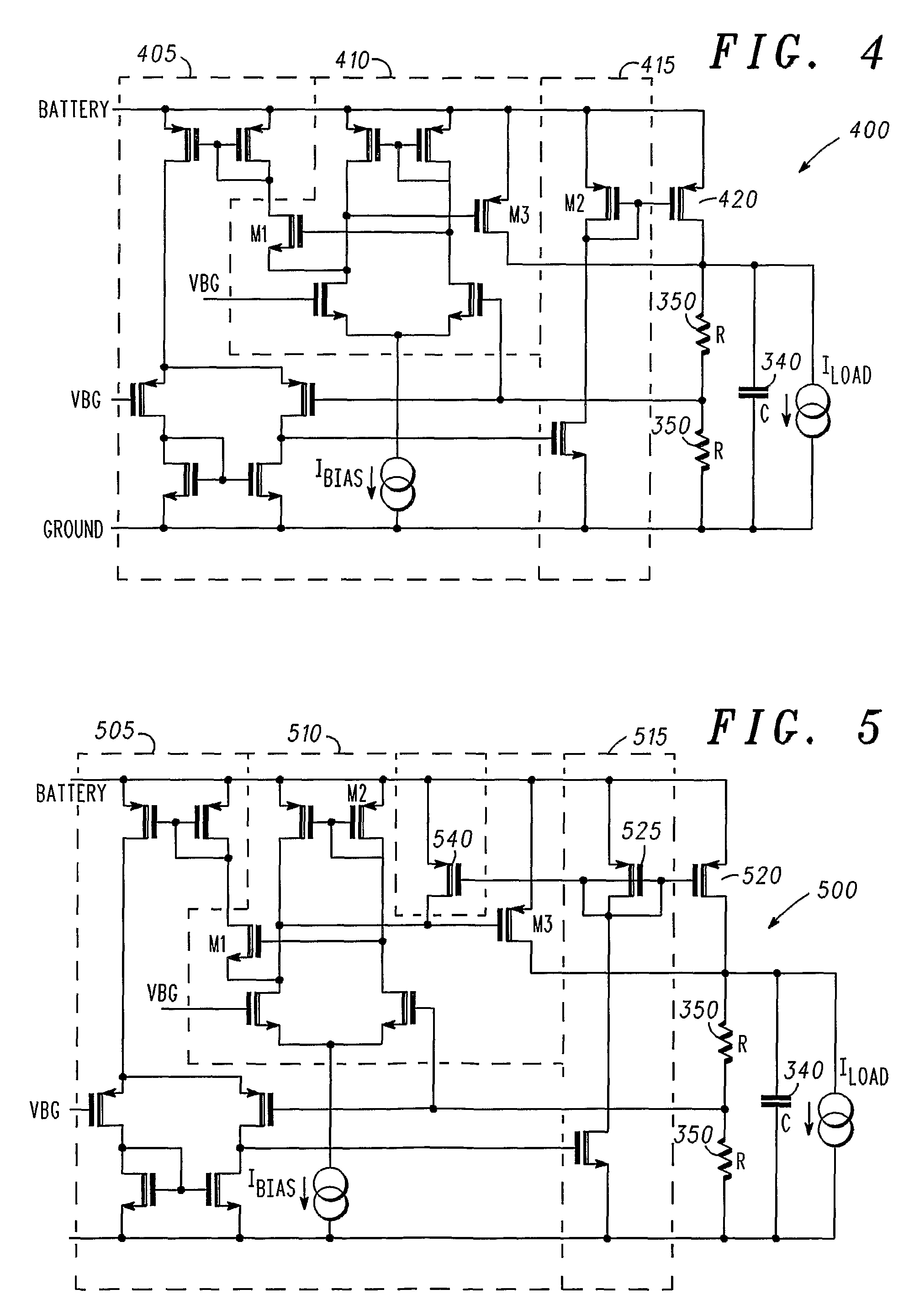
[0038]In summary, the preferred embodiment of the present invention provides a voltage regulator that is divided into two distinct sub-regulators, effectively operating in parallel. In this manner, a first sub-regulator of the preferred embodiment is capable of providing a low quiescent current (Icc) regulator for low loads, with the second sub-regulator effectively supporting other load currents.

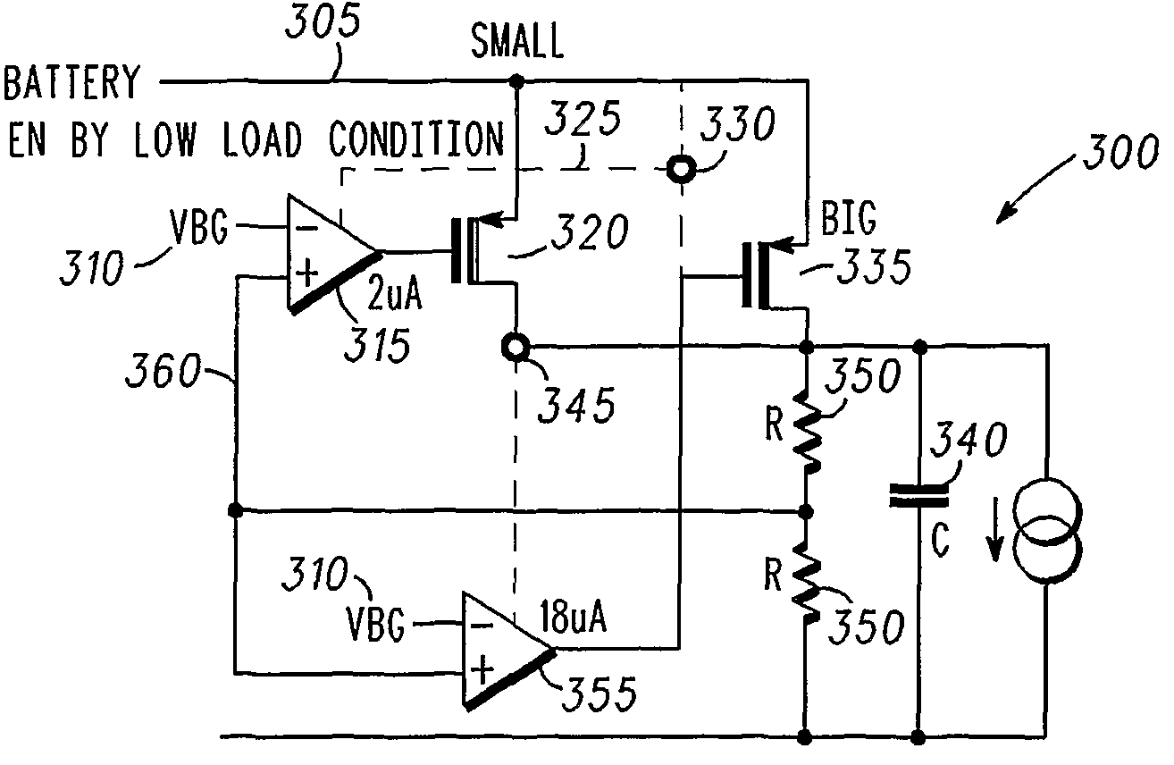
[0039]Advantageously, an architecture is provided that facilitate an automatic optimization of the regulation loop in response to the load. The architecture is based on the same fundamental principle of operation, as illustrated in the voltage regulator architecture 300 of FIG. 3.

[0040]The voltage regulator architecture 300 of the preferred embodiment of the present invention, as illustrated in FIG. 3, uses a double loop architecture. A first loop is configured to perform the main voltage regulator operation, which is the high current mode of operation and referred to as the ‘main loop’. Fo...


PUM


Abstract

A voltage regulator for providing a voltage regulated output to a load comprises a first loop and a second loop. The first loop comprises a first active device coupled to a first pass device and configured to provide a first, relatively high current output to the load. The second loop comprises a second active device coupled to a second pass device and configured to provide a second, relatively low current output to the load. This provision of two independent loops reduces the quiescent current provided by the voltage regulator under low load conditions.

Description

FIELD OF THE INVENTION[0001]This invention relates to voltage regulators. The invention is applicable to, but not limited to, improving the performance of a voltage regulator over the range of possible loads supported by the voltage regulator.BACKGROUND OF THE INVENTION[0002]A low drop-out (LDO) voltage regulator is a regulator circuit that provides a well-specified and stable DC voltage (whose input-to-output voltage difference is typically low). The operation of the circuit is based on feeding back an amplified error signal, which is used to control output current flow of a ‘pass’ device (such as a power transistor) driving a load. The drop-out voltage is the value of the input / output differential voltage where regulation is lost.[0003]The low drop-out nature of the regulator makes it more appropriate, in contrast to other types of regulators such as dc-dc converters and switching regulators, for use in many applications, such as automotive, portable, and industrial applications. ...

Claims


Application Information

Patent Timeline
Patent Type & Authority Patents(United States)
IPC IPC(8): G05F1/40
CPCG05F1/565
Inventor ODDOART, LUDOVICTRAUTH, GERHARD
Owner NXP USA INC
Learn More