
Buoyancy neutral fiber optic cable

a fiber optic cable, neutral technology, applied in the field of communication cables, can solve the problems of significant signal loss, overall signal attenuation, and small rovs are particularly susceptible to the buoyancy of the cable, and achieve the effect of neutral buoyancy in water

Inactive Publication Date: 2010-10-26
COMMSCOPE INC
View PDF21 Cites 7 Cited by
  • Summary
  • Abstract
  • Description
  • Claims
  • Application Information

AI Technical Summary

Benefits of technology

The present invention provides a fiber optic cable that is well-suited for harsh environments, such as undersea environments. The cable is designed to have neutral buoyancy in water and is constructed to have improved hockling resistance and tensile strength. The cable includes a single mode optical fiber surrounded by a suspension fluid and strength members. The cable may also have an inner containment tube and an outer jacket. The technical effects of the invention include improved signal quality, reduced signal loss, and better protection for the optical fiber.

Problems solved by technology

The deformation can result in significant signal loss, e.g. when the incident angle is less than the critical angle, the light no longer reflects internally, but is reflected out of the core and a signal loss occurs at the point of the deformation, which leads to an overall signal attenuation.
Smaller ROVs are particularly susceptible to the buoyancy of the cable.
As cable is paid out, a shift in the buoyancy can cause the ROV to rise or fall in the water.
Both circumstances were less than optimal.

Method used


Image

  • Buoyancy neutral fiber optic cable
  • Buoyancy neutral fiber optic cable
  • Buoyancy neutral fiber optic cable

Examples


first embodiment

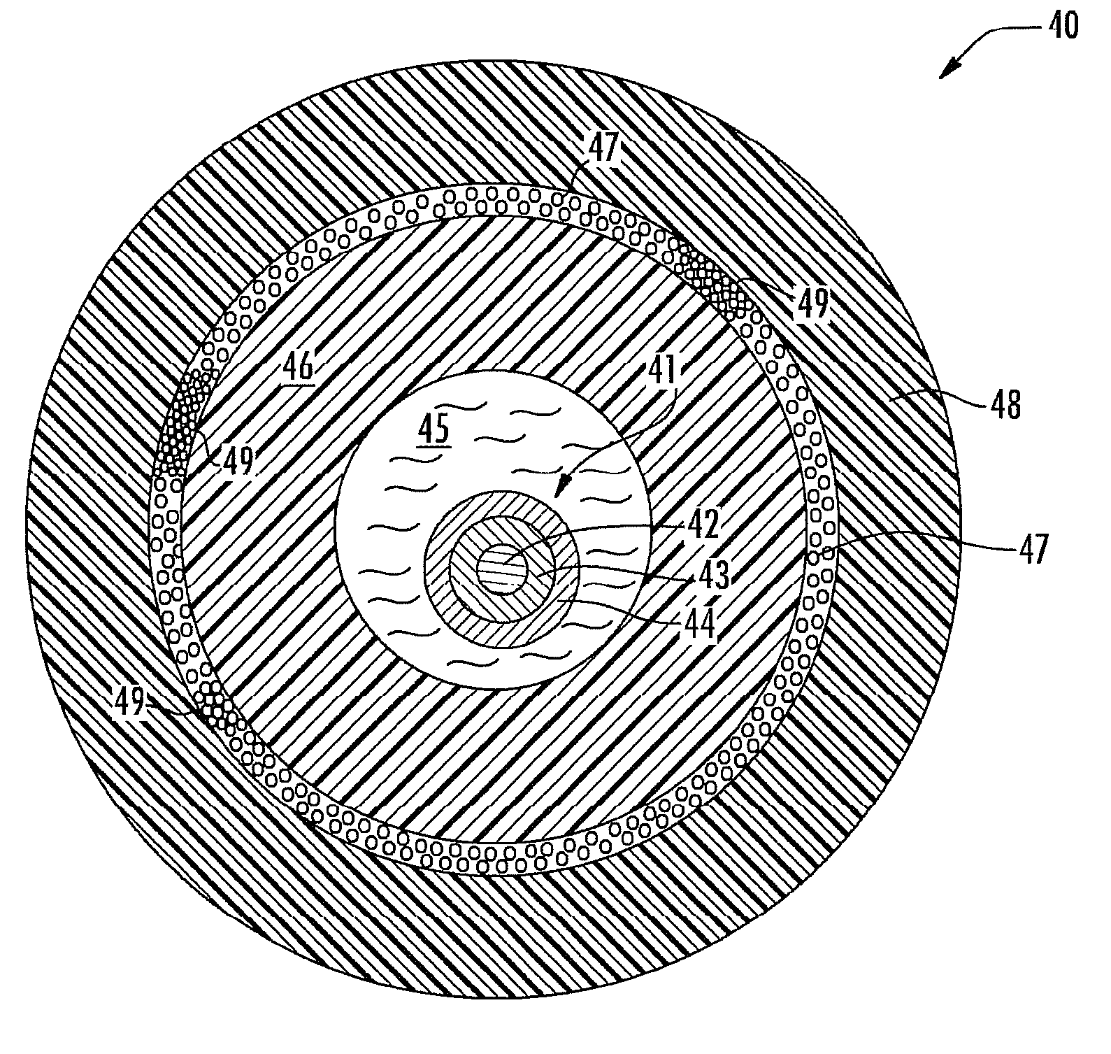
[0034]FIGS. 9 and 10 illustrate a fiber optic cable 40, in accordance with the present invention. The fiber optic cable 40 includes a single optical fiber 41, containing a core 42 and a cladding layer 43 surrounding the core, with one or more polymer coatings 44 applied over the cladding layer 43, such that the optical fiber 41 assumes a diameter of 250 um.

[0035]A suspension liquid 45 surrounds the optical fiber 41. In a preferred embodiment, the suspension liquid 45 is a form of Carnation light mineral oil. It is possible that other types of suspension fluids besides pure mineral oil could be substituted, such as a blend of oil and silica, like Gel R-1871, as manufactured by Master Adhesives of Norcross, Ga. However, it is believed that pure Carnation mineral oil is best suited for the fiber optic cable 40, as gels are more problematic in the manufacturing of the fiber optic cable 40 due to the more viscous nature of the gel.

[0036]An inner containment tube 46 surrounds and contains...

second embodiment

[0043]Specifically, the fiber optic cable 50 includes the single optical fiber 41, containing the core 42 and the cladding layer 43 surrounding the core, with one or more polymer coatings 44 applied over the cladding layer 43, such that the optical fiber 41 assumes a diameter of 250 um. The suspension liquid 45 surrounds the optical fiber 41. The inner containment tube 46 surrounds and contains the suspension fluid 45. The plurality of strength members 47 surrounds the inner containment tuber 46. However, in the second embodiment, the strength members 47 are thin fibers, which are braided into groups about the inner containment tube 46.

[0044]The braiding of thin wires is known in the coaxial cable art, for forming shielding layers for coaxial cables. It is envisioned that the same or similar techniques could be used to braid the strength members 47 (e.g., aramid yarn fibers) as employed in the preferred embodiment of the present invention. The depth of the braided layer of strength ...


PUM


Abstract

A robust fiber optic cable is well suited for harsh environments, such as undersea environments, as a communication link to a mobile undersea vehicle. In preferred embodiments, the fiber optic cable is constructed to have neutral buoyancy in salt water. The fiber optic cable may include one single mode optical fiber. A suspension fluid, such as light mineral oil surrounds the optical fiber. In an optional embodiment, a plurality of strength members also surrounds the optical fiber and these elements are surrounded by an outer jacket. In another optional embodiment, the optical fiber and suspension fluid may be loosely surrounded by an inner containment tube, a plurality of strength members surrounds the inner containment tube, and these elements are surrounded by an outer jacket, which may be bonded to the inner containment tube.

Description

[0001]This application is a continuation-in-part of prior application Ser. No. 11 / 621,013, filed Jan. 8, 2007 now U.S. Pat. No. 7,489,844, the entire contents of which are herein incorporated by reference.BACKGROUND OF THE INVENTION[0002]1. Field of the Invention[0003]The present invention relates to communication cables. More particularly, the present invention relates to a fiber optic cable, suitable for connection to a moving object used in deep-sea exploration.[0004]2. Description of the Related Art[0005]A remotely operated underwater vehicle (ROV) is known in the prior art. An ROV is typically operated by a person aboard a ship or submarine, and is tethered to the ship or submarine by at least a power cable and a communication cable. The power cable supplies power for ROV motors, lights, cameras, manipulation arms, etc. The communication cable carries control signals to the ROV for maneuvering the ROV, and information signals from the ROV to the operator, such as video signals,...

Claims


Application Information

Patent Timeline
Patent Type & Authority Patents(United States)
IPC IPC(8): G02B6/44
CPCG02B6/4427G02B6/4432G02B6/4483
Inventor SHINOSKI, JARRETTSIGMON, KEVIN
Owner COMMSCOPE INC
Learn More