Electronic sign having a formed metal cabinet

Active Publication Date: 2010-11-02
DAKTRONICS
View PDF32 Cites 48 Cited by
  • Summary
  • Abstract
  • Description
  • Claims
  • Application Information

AI Technical Summary

Benefits of technology

[0008]The general purpose of the present invention is to provide an electronic sign having a formed metal cabinet, whereby the cabinet can be fabricated using precision formed channels, precision formed panels, and the like. A plurality of formed components, which can include precision cut or stamped channels, is combined to make a formed metal cabinet for use with electronic display modules to provide an electronic sign having a formed metal cabinet. The components are considered to be formed components made by precise cutting, stamping, bending, laser cutting, and the like in order to provide uniformly shaped components of close tolerance and fit which can be planar two dimensional components or which can be multiple faced components in more than one plane. A plurality of vertically oriented formed channels and formed mid-channels is secured and aligned between a formed top channel and a formed bottom channel. Formed top, bottom and end panels include a plurality of different sized counterbored holes which can accommodate the flush mounting of rivet heads or nut insert heads. A double-sided adhesive coated tape is used to secure and seal the formed top, bottom, and end panel

Problems solved by technology

Prior art electronic signs included a cabinet structure which was labor intensive in constructing and, therefore, time consuming, requiring alignment of components and subsequent drilling, riveting, welding and other techniques.
In addition, the c

Method used


Image

  • Electronic sign having a formed metal cabinet
  • Electronic sign having a formed metal cabinet
  • Electronic sign having a formed metal cabinet

Examples


Embodiment Construction

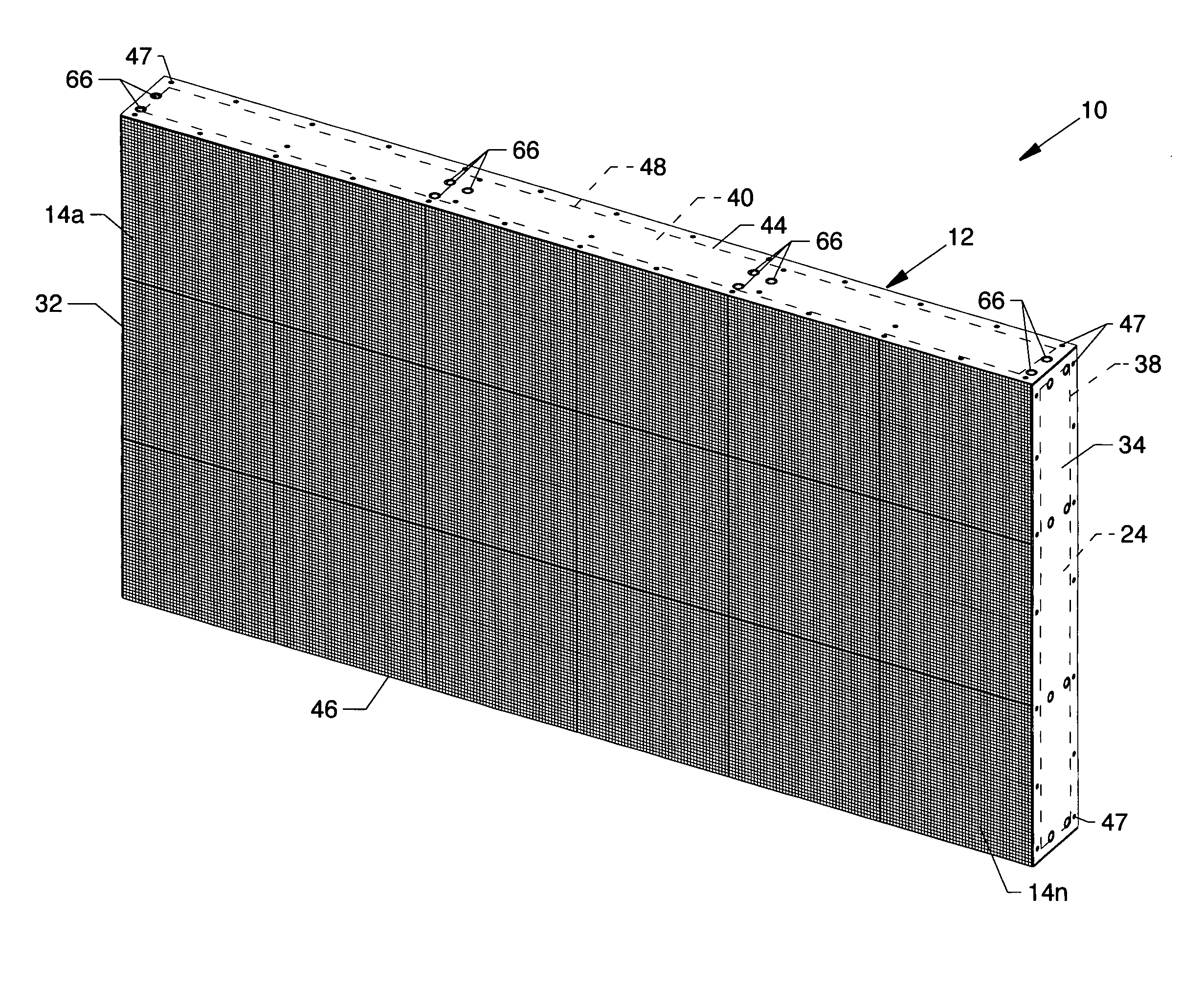
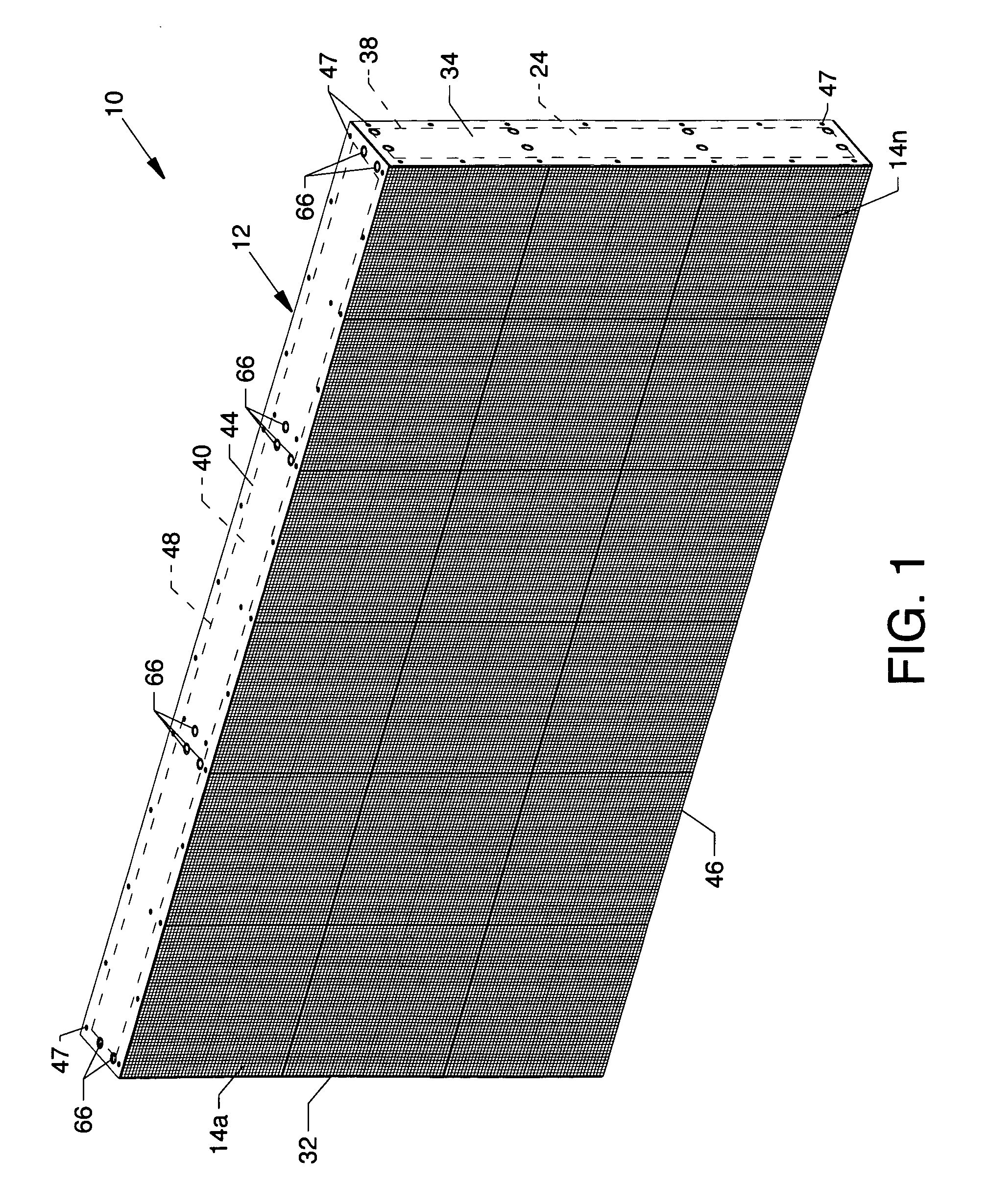
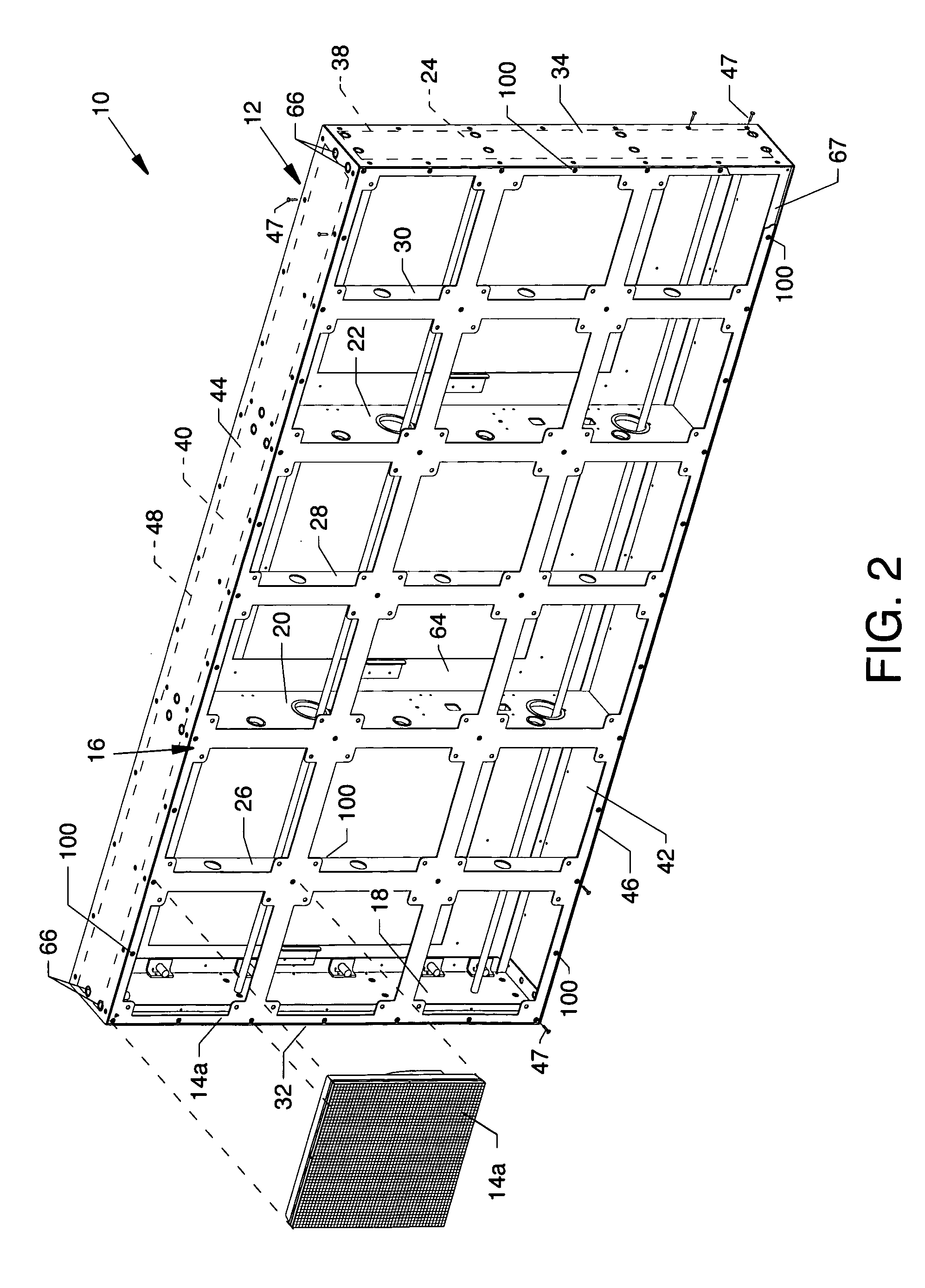
[0042]FIG. 1 is a front isometric view of an electronic sign 10 having a formed metal cabinet 12, the present invention. A plurality of electronic display modules having a four-point latching system, herein referred to as the display modules 14a-14n, removably attach to the front of a formed metal cabinet 12. FIG. 2 is a front isometric view of an electronic sign having a formed metal cabinet 12 where only one display module 14a is shown distanced from a mounting panel 16. The mounting panel 16, a part of the formed metal cabinet 12, is used to mount the plurality of display modules 14a-14n. The relationship of the mounting panel 16 and the display modules 14a-14n is described in U.S. Pat. No. 7,055,271 entitled “Electronic Display Module Having a Four-Point Latching System for Incorporation into an Electronic Sign and Process”. Other components of the formed metal cabinet 12 are viewable through the structure of the mounting panel 16 and are described later in detail, whereby refer...


PUM


Abstract

An electronic sign having a formed metal cabinet where precise and close tolerance formed planar panels and formed channels are fastened together only by rivets, nut inserts, adhesive coated tapes, or the combination thereof for rapid assembly thereof.

Description

CROSS REFERENCES TO RELATED APPLICATIONS[0001]This patent application is a continuation-in-part (CIP) of application Ser. No. 11 / 809,107 filed May 31, 2007, entitled “Electronic Sign Having a Formed Metal Cabinet”, which is pending.[0002]This application claims priority from the earlier filed U.S. Provisional Application No. 60 / 961,832 filed Jul. 24, 2007, entitled “Electronic Sign Having a Formed Metal Cabinet”, and is hereby incorporated into this application by reference as if fully set forth herein.[0003]This application is related to U.S. utility patent application Ser. No. 10 / 688,304 filed Oct. 17, 2003, entitled “Electronic Display Module Having a Four-Point Latching System for Incorporation into an Electronic Sign and Process”, now U.S. Pat. No. 7,055,271 to Lutz et al., patented Jun. 6, 2006, which is incorporated herein by reference.BACKGROUND OF THE INVENTION[0004]1. Field of the Invention[0005]The present invention is for an electronic sign, and more particularly, pertai...

Claims


Application Information

Patent Timeline
IPC IPC(8): G09F9/00
CPCH05K5/04H05K7/183
Inventor MUNSON, LANE A.FULS, CASSANDRA L.
Owner DAKTRONICS
Why Eureka
Try Eureka