Operating device for a vehicle

a technology for operating devices and vehicles, applied in the direction of mechanical control devices, manual control with single controlling member, instruments, etc., to achieve the effect of improving the operation of vehicles and implements

Active Publication Date: 2010-11-02
DEERE & CO
View PDF44 Cites 29 Cited by
  • Summary
  • Abstract
  • Description
  • Claims
  • Application Information

AI Technical Summary

Benefits of technology

[0004]The object of the present invention is therefore to provide and further develop an operating device of the above-mentioned type so as to overcome the above-stated problems. In particular, the operating device according to the invention needs to enable ergonomic operation, so as to improve operation of the vehicle and of the implement.
[0006]According to the invention, it was firstly recognized that simultaneous operation of the vehicle and of the implement is possible just with two hands, i.e. without foot actuation, if at least one operating element for driving the implement is also provided on the control lever with which the vehicle speed is adjusted. It is not then necessary for the operator to swap between two operating devices, namely the joystick for driving the front end loader and the control lever for adjusting the vehicle speed, in order to achieve more or less simultaneous operation of vehicle and implement. By providing the at least one operating element for driving the implement on the control lever, it is possible in advantageous manner on the one hand to adjust or modify the vehicle speed and on the other hand to drive the implement. Thus, the operator may control the steering wheel with one hand while actuating the control lever with the other hand on the one hand to act on the vehicle speed and on the other hand to drive the implement, this being possible at the same time and without swapping to another control lever. It is no longer necessary for the operator to actuate the accelerator pedal with a foot in order to modify the vehicle speed. Instead, the operator can have one foot positioned ready to react on the brake pedal, such that the operator can react more quickly if need be, which is safer. In this way, simple and—after a short training phase—also intuitive operation of the vehicle and of the implement is possible. This operating concept is additionally ergonomic and an operator can operate the vehicle over a relatively long period with the operating device according to the invention without becoming tired as a result.
[0013]The one deflection direction could be oriented substantially parallel to the longitudinal control lever adjustment direction. The other deflection direction could be oriented substantially perpendicularly thereto. Thus, the direction of deflection of the joystick is coupled with the possibility of adjusting the control lever in its longitudinal direction. This encourages intuitive operation of the operating device.
[0015]Moreover, the control lever could have a longitudinal axis. The joystick could be movable in the direction of the longitudinal axis of the control lever. This could be associated with a drive functionality and / or a safeguarding functionality upon driving of the implement. Thus, for example, it could be provided that the implement is drivable only when the joystick is pressed downwards in the direction of the longitudinal axis of the control lever and is accordingly driven in accordance with the desired drive functionality by deflection of the joystick. In this way inadvertent actuation of the joystick could be at least largely avoided.
[0019]According to one embodiment, the control lever comprises an operating element for activating and deactivating drive of the implement. Such an operating element could likewise be provided for safety purposes, such that the implement is not inadvertently actuated when all that is intended is actuation of the control lever to adjust the vehicle speed. In practice, such an operating element could also be constructed in such a way that actuation of the operating element is necessary in order to bring the control lever into the catch position or move it out of the catch position.

Problems solved by technology

This means actuating three different operating devices simultaneously, which can be tiring in the long run and / or requires a relatively long training phase until the operator can operate the vehicle optimally with the implement fitted.

Method used


Image

  • Operating device for a vehicle
  • Operating device for a vehicle
  • Operating device for a vehicle

Examples


Embodiment Construction

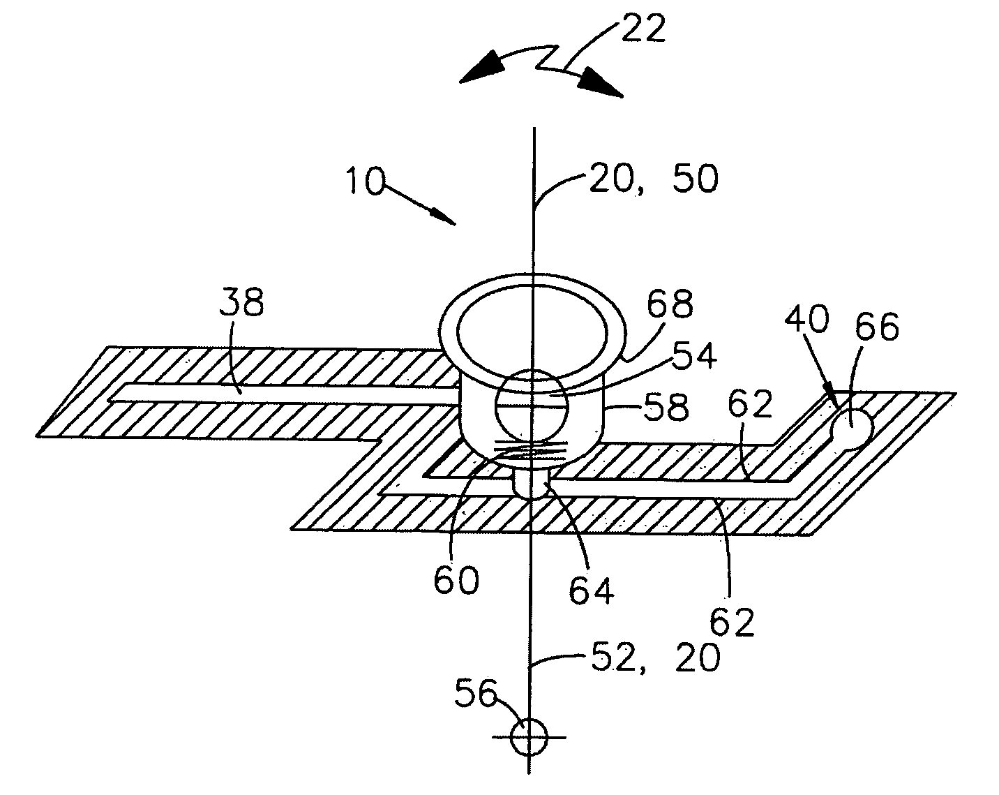
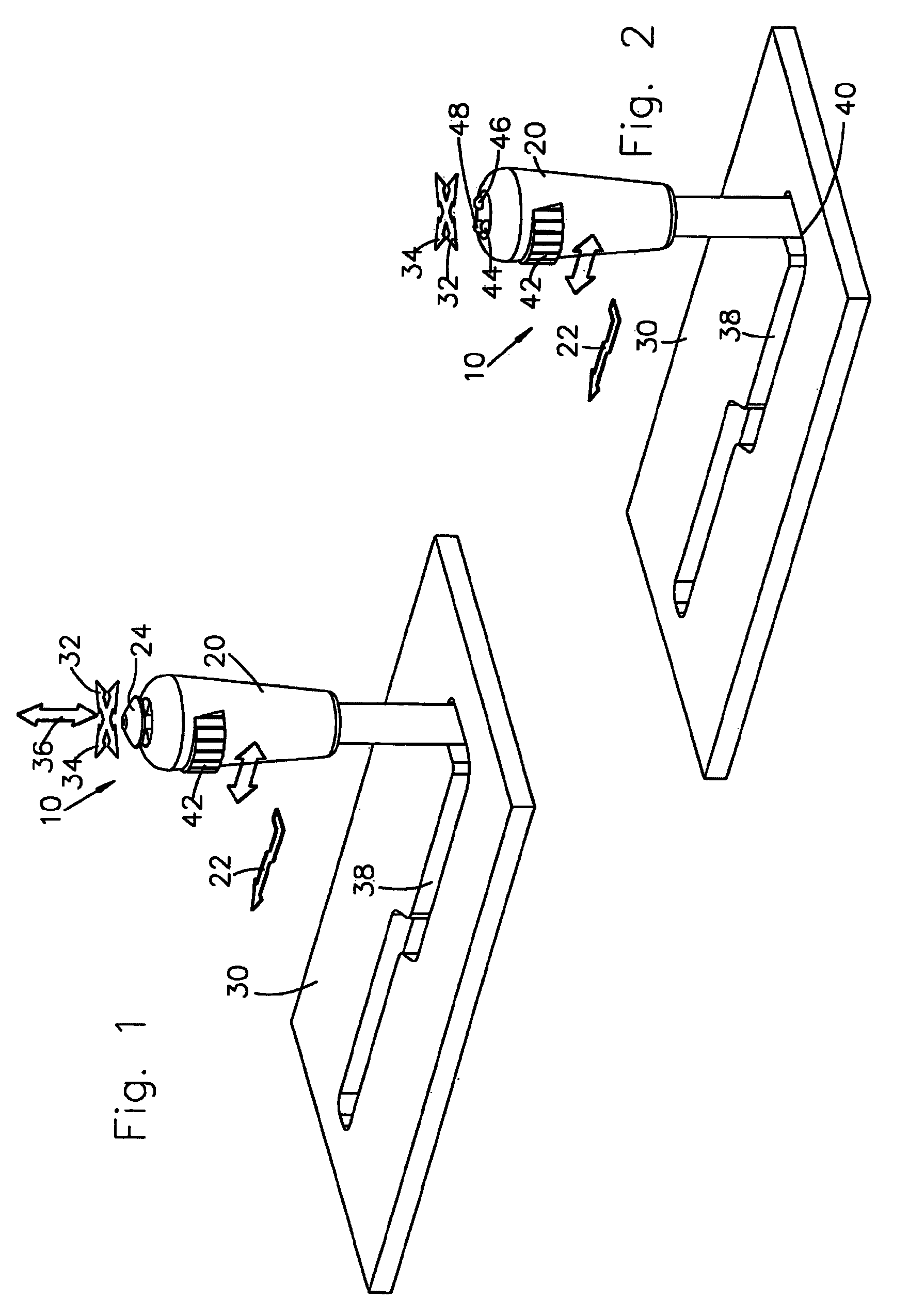
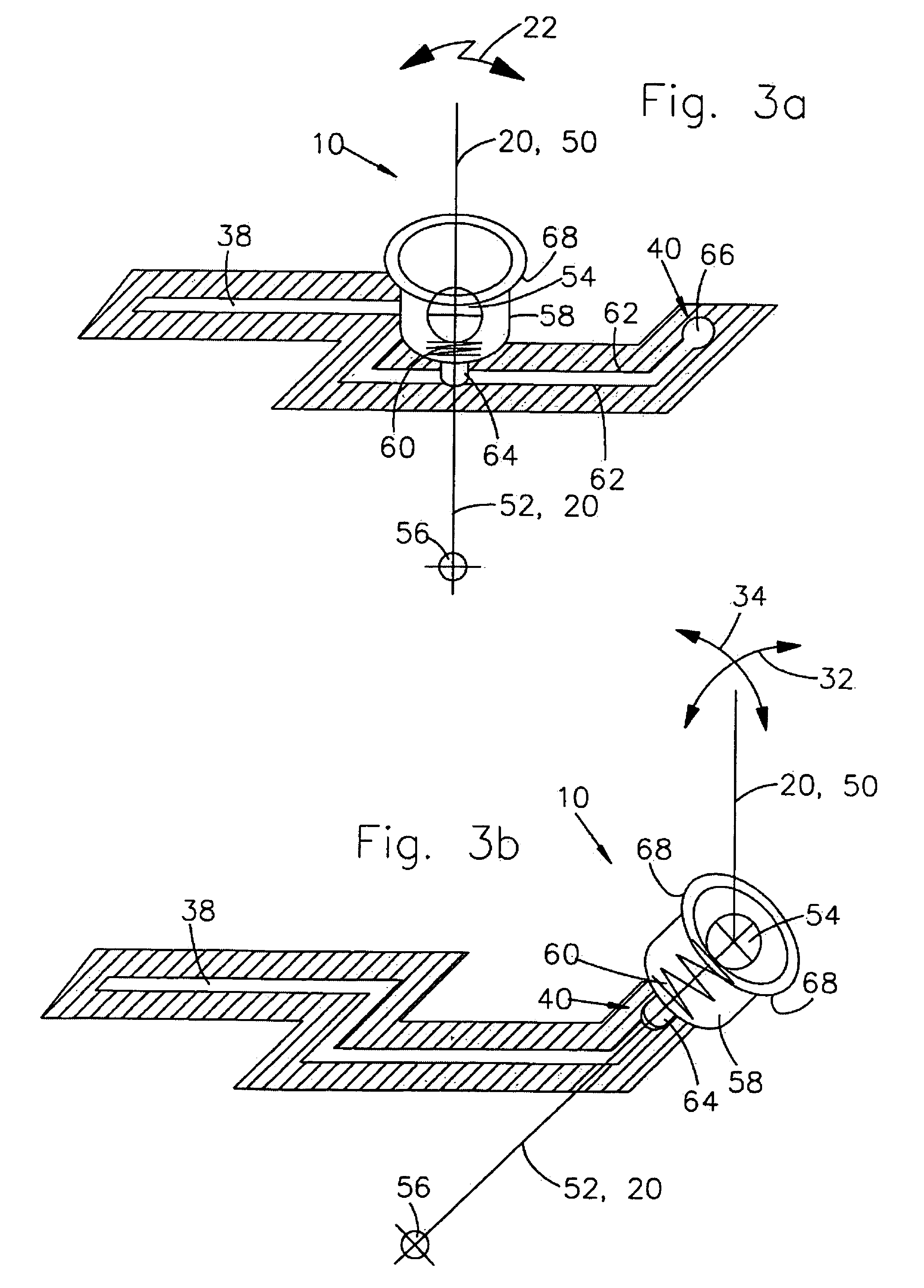
[0027]FIG. 1 shows a first exemplary embodiment of an operating device 10 according to the invention for a vehicle 12 (FIG. 4). The vehicle 12 shown in FIG. 4 is a tractor 12 with an implement in the form of a loading device 14. The loading device 14 comprises a boom 16, which is coupled rotatably with its one end to the tractor 12 and which comprises at its other end a loader tool 18 in the form of a shovel. The loading device 14 comprises two hydraulic actuators 26 (on the left- and right-hand sides of the tractor 12, just one actuator being shown in FIG. 4), which take the form of hydraulic cylinders and with which the boom 16 may be rotated relative to the tractor 12. The loading device 14 is attached to an implement interface 28 provided on the tractor 12, which interface 28 is known per se from the prior art.

[0028]The operating device 10 comprises a manually actuatable control lever 20. The speed of the vehicle can be adjusted using the control lever 20. To this end, the contr...


PUM


Abstract

An operating device is provided for a vehicle, in particular for an agricultural or industrial utility vehicle. The operating device comprises a manually actuatable control lever. The control lever is used to adjust or modify the speed of the vehicle. The control lever is adjustable in a longitudinal direction, in order to adjust the speed of the vehicle. An implement with which at least one working function may be performed may be fitted to the vehicle. In order to enable ergonomic operation, it is proposed that the control lever comprise at least one operating element, with which the implement may be driven, and that the operating element be arranged so as to be movable together with the control lever in the longitudinal direction.

Description

FIELD OF THE INVENTION[0001]The invention relates to an operating device for a vehicle, in particular for an agricultural or industrial utility vehicle. For instance, the vehicle could take the form of a construction machine, a telescopic loader, a tractor with front end loader or a tractor with an implement fitted thereto. The operating device comprises a manually actuatable control lever. The control lever is used to adjust or modify the speed of the vehicle. This could proceed, for example, through variation or adjustment of the engine speed and / or the gear ratio, a combination of adjustment of the engine speed and of the gear ratio being sensible particularly in the event of changes in the loads acting on the vehicle. The control lever is adjustable in a longitudinal direction, in order to adjust or modify the speed of the vehicle. To this end, at least one sensor can be provided on the control lever and / or on the console, which sensor detects the current position of the control...

Claims


Application Information

Patent Timeline
Patent Type & Authority Patents(United States)
IPC IPC(8): B62D1/12G05G9/047
CPCA01B63/00E02F9/2004G05G9/047F16H59/06Y10T74/20201G05G2009/04777G05G2009/04781F16H59/0278Y10T74/20396G05G2009/04774
Inventor BLIND, ALAINSCHORRY, GERD
Owner DEERE & CO
Why Eureka
Try Eureka