Airfoil prognosis for turbine engines
a turbine engine and prognosis technology, applied in the direction of liquid fuel engines, machines/engines, instruments, etc., can solve the problems of airfoil cracks, blades, no system, etc., and achieve the effect of less stressful operation
- Summary
- Abstract
- Description
- Claims
- Application Information
AI Technical Summary
Benefits of technology
Problems solved by technology
Method used
Image
Examples
Embodiment Construction
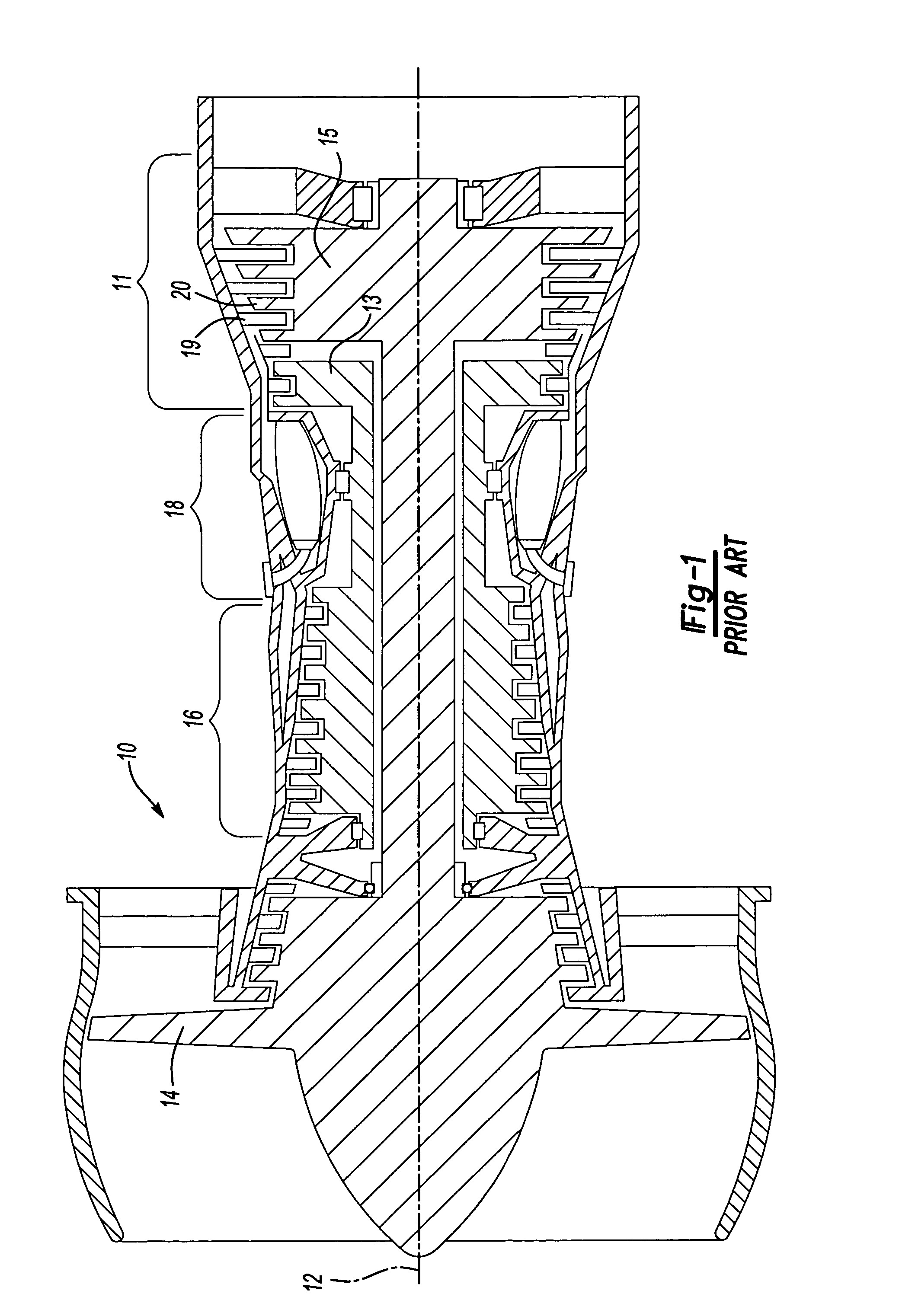
[0017]FIG. 1 shows a gas turbine engine 10, such as a gas turbine used for power generation or propulsion, circumferentially disposed about an engine centerline, or axial centerline axis 12. The engine 10 includes a fan 14, a compressor 16, a combustion section 18 and a turbine 11. As is well known in the art, air compressed in the compressor 16 is mixed with fuel which is burned in the combustion section 18 and expanded in turbine 11. The air compressed in the compressor and the fuel mixture expanded in the turbine 11 can both be referred to as a hot gas stream flow. The turbine 11 includes rotors 13 and 15 that, in response to the expansion, rotate, driving the compressor 16 and fan 14. The turbine 11 comprises alternating rows of rotary blades 20 and static airfoils or vanes 19. FIG. 1 is a somewhat schematic representation, for illustrative purposes only, and is not a limitation of the instant invention, that may be employed on gas turbines used for power generation and aircraft...
PUM
 Abstract
Description
Claims
Application Information
 - R&D
- Intellectual Property
- Life Sciences
- Materials
- Tech Scout
- Unparalleled Data Quality
- Higher Quality Content
- 60% Fewer Hallucinations
Browse by: Latest US Patents, China's latest patents, Technical Efficacy Thesaurus, Application Domain, Technology Topic, Popular Technical Reports.
© 2025 PatSnap. All rights reserved.Legal|Privacy policy|Modern Slavery Act Transparency Statement|Sitemap|About US| Contact US: help@patsnap.com


