Optical modulation apparatus

a technology of optical modulation and optical components, applied in the direction of optical elements, electromagnetic transceivers, instruments, etc., can solve the problems of large circuitry, complicated control process, and inability to provide the optimal operating point of bias voltage, so as to simplify the control process and scale down the circuitry

Inactive Publication Date: 2010-11-02
FUJITSU LTD
View PDF2 Cites 9 Cited by
  • Summary
  • Abstract
  • Description
  • Claims
  • Application Information

AI Technical Summary

Benefits of technology

[0028]In view of the foregoing, it is an object of the present invention to provide an optical modulation apparatus that controls a bias voltage for optimum optical modulation without using a pilot tone, making it possible to scale down the circuitry and simplify the control process.

Problems solved by technology

If the frequency component of the pilot tone appears in the electric signal, the bias voltage does not provide the optimum operating point.
These operations require large circuitry.
This results in large circuitry and complicated control process.

Method used


Image

  • Optical modulation apparatus
  • Optical modulation apparatus
  • Optical modulation apparatus

Examples


Embodiment Construction

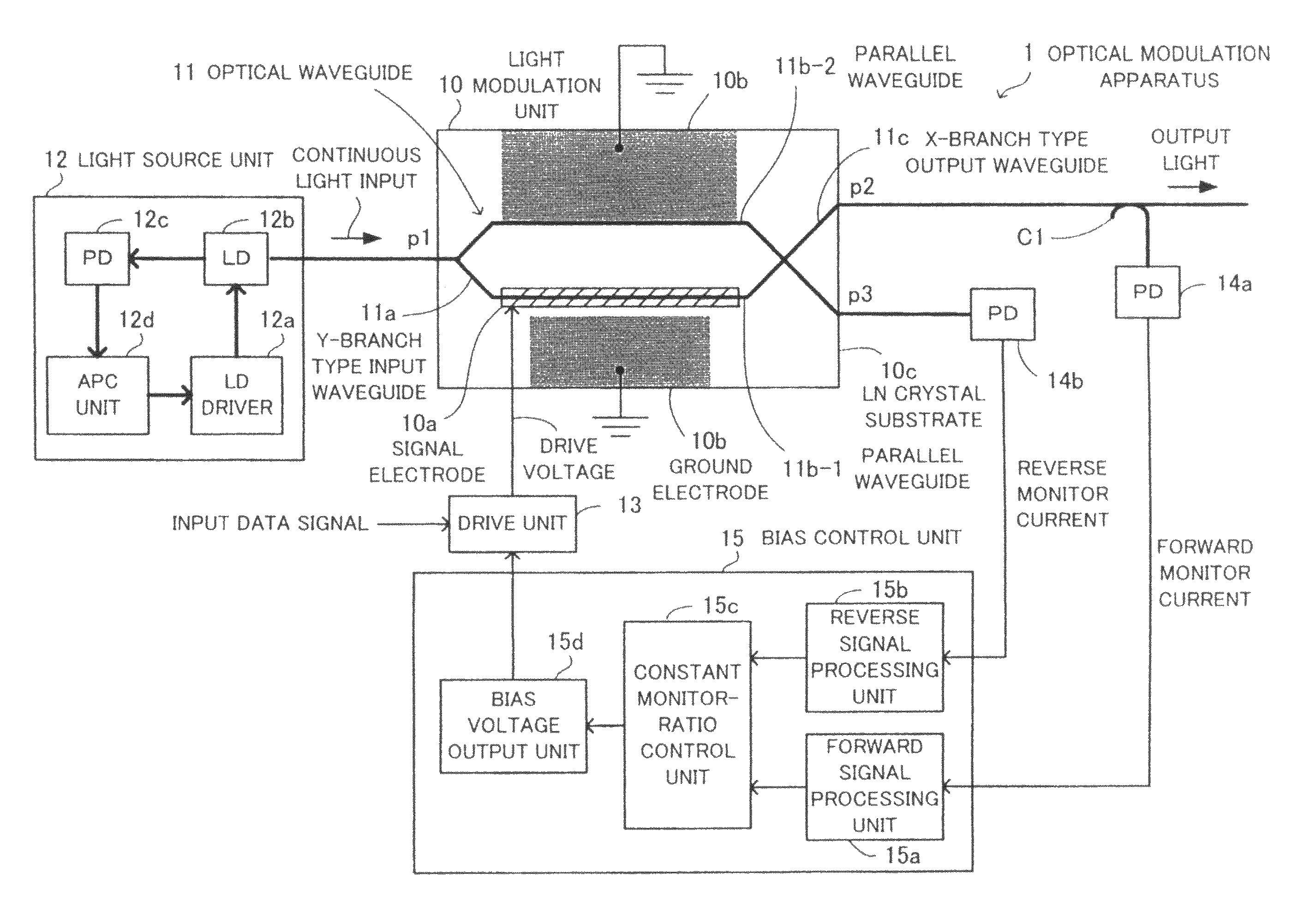
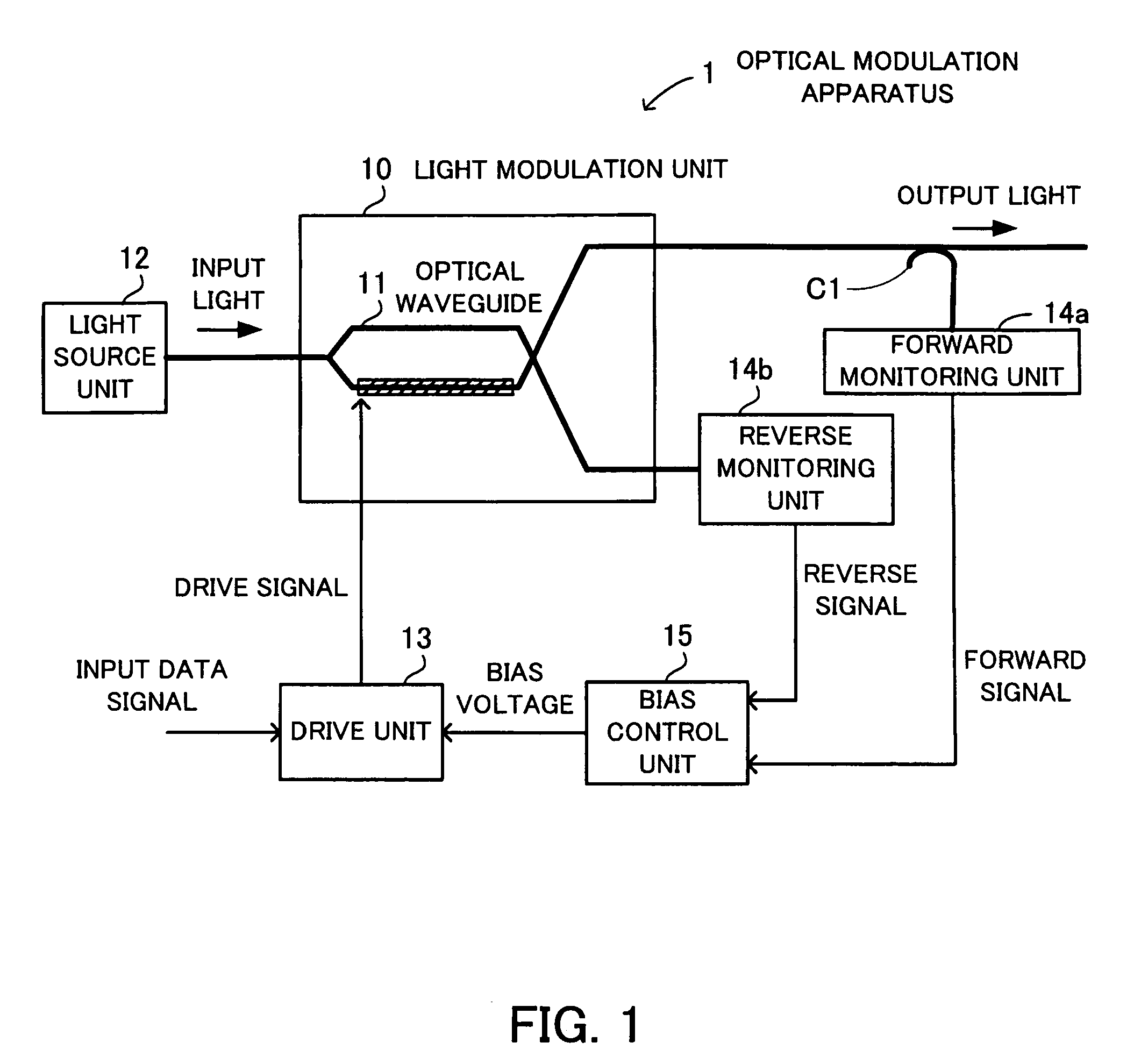
[0045]Embodiments of the present invention will be described with reference to the drawings. FIG. 1 shows the basic concept of an optical modulation apparatus 1. The optical modulation apparatus 1 for performing optical modulation includes a light modulation unit 10 that includes an optical waveguide 11 of Mach-Zehnder interferometer type, a light source unit 12, a drive unit 13, a coupler C1, a forward monitoring unit 14a, a reverse monitoring unit 14b, and a bias control unit 15.

[0046]The drive unit 13 generates a drive signal by adding a bias voltage to an input data signal. The light modulation unit 10 modulates continuous light output from the light source unit 12 in accordance with the drive signal and outputs the results as optical signals.

[0047]The forward monitoring unit 14a monitors a forward optical signal output from the light modulation unit 10 and split by the coupler C1 and outputs the monitored value as an electric forward signal. The reverse monitoring unit 14b moni...


PUM

PropertyMeasurementUnit
currentaaaaaaaaaa
currentaaaaaaaaaa
operating temperatureaaaaaaaaaa

Abstract

An optical modulation apparatus that performs optimum bias voltage control for optical modulation without using a pilot tone. A drive unit generates a drive signal by adding a bias voltage to an input data signal. A light modulation unit modulates input light output from a light source unit, in accordance with the drive signal, and outputs the results as optical signals. A forward monitoring unit monitors a forward signal of the light modulation unit and outputs the forward signal. A reverse monitoring unit monitors a reverse signal of the light modulation unit and outputs a reverse signal. A bias control unit controls the bias voltage so that a measured monitor ratio matches a target value of the ratio between the forward signal and the reverse signal, obtained when the operating point of the light modulation unit is in a predetermined position on its operation characteristic curve.

Description

CROSS-REFERENCE TO RELATED APPLICATIONS[0001]This application is based upon and claims the benefits of priority from the prior Japanese Patent Application No. 2008-140834, filed on May 29, 2008, the entire contents of which are incorporated herein by reference.BACKGROUND OF THE INVENTION[0002]1. Field of the Invention[0003]The present invention relates to optical modulation apparatuses for performing optical modulation.[0004]2. Description of the Related Art[0005]Optical devices widely used in optical communication include optical modulators. In some optical modulators, an optical waveguide is formed on a substrate, and an input electric signal is converted to an optical signal by applying the voltage to the optical waveguide to change the amount of light absorption on the optical waveguide, thereby modulating the light intensity (external modulation).[0006]FIG. 11 shows the structure of a conventional optical modulator 5. The optical modulator 5 includes a light source 50, an exter...

Claims


Application Information

Patent Timeline
Patent Type & Authority Patents(United States)
IPC IPC(8): G02F1/01G02F1/03G02F1/035H04B10/07H04B10/40H04B10/50H04B10/516H04B10/54H04B10/564H04B10/60H04B10/61
CPCG02F1/0123G02F1/2255
Inventor MORISHITA, TSUYOSHI
Owner FUJITSU LTD
Why Eureka
Try Eureka