Level shifter

Active Publication Date: 2012-03-01
SAMSUNG ELECTRO MECHANICS CO LTD
View PDF2 Cites 8 Cited by
  • Summary
  • Abstract
  • Description
  • Claims
  • Application Information

AI Technical Summary

Benefits of technology

[0012]An aspect of the present invention provides a level shifter in which a plurality of amplifiers are connected in paralle

Problems solved by technology

Therefore, the conventional level shifter may not me

Method used


Image

  • Level shifter
  • Level shifter
  • Level shifter

Examples


Embodiment Construction

[0022]Exemplary embodiments of the present invention will now be described in detail with reference to the accompanying drawings. The invention may, however, be embodied in many different forms and should not be construed as being limited to the embodiments set forth herein. Rather, these embodiments are provided so that this disclosure will be thorough and complete, and will fully convey the scope of the invention to those skilled in the art. In the drawings, the thicknesses of layers and regions are exaggerated for clarity. Like reference numerals in the drawings denote like elements, and thus their description will be omitted.

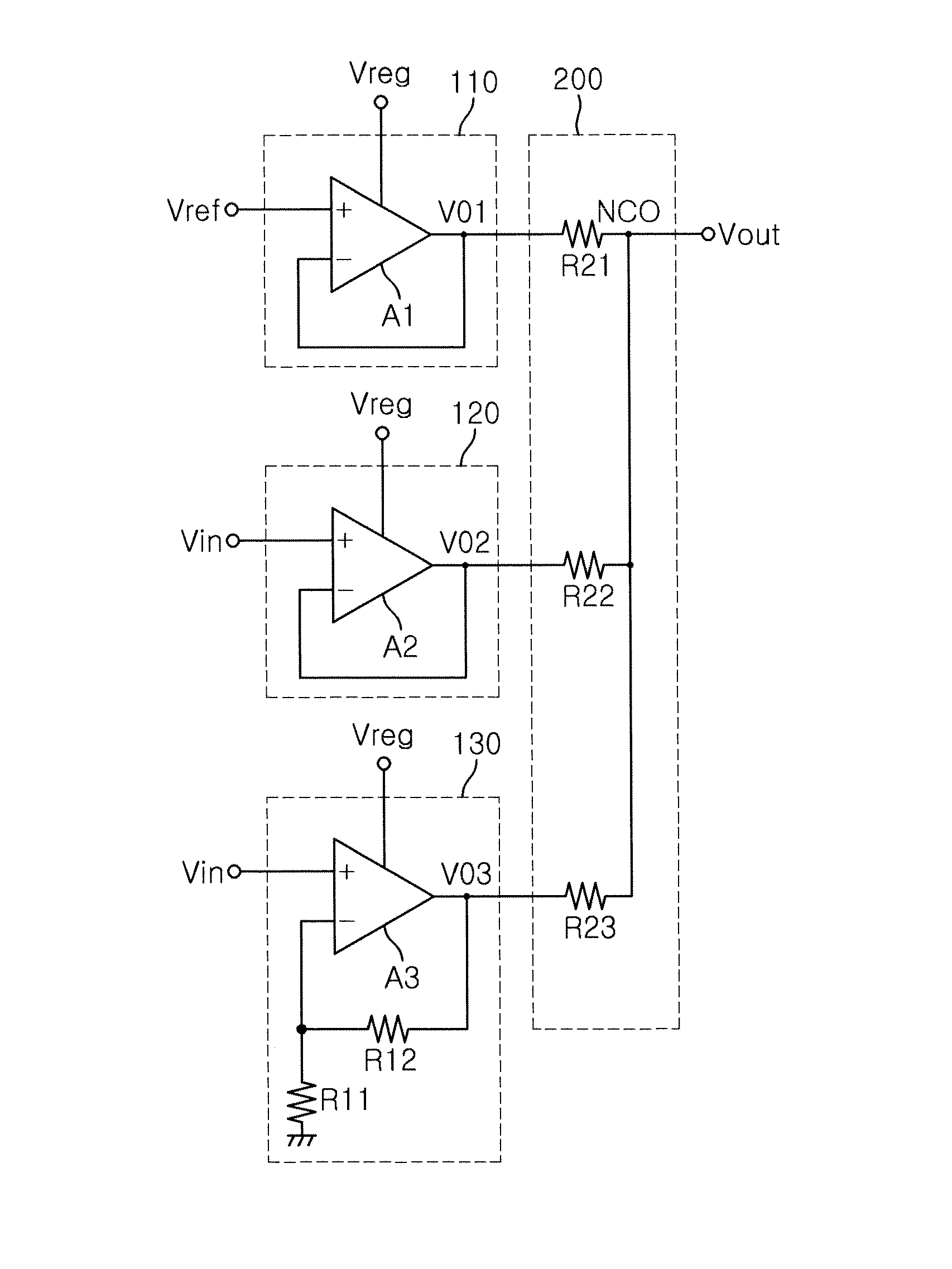
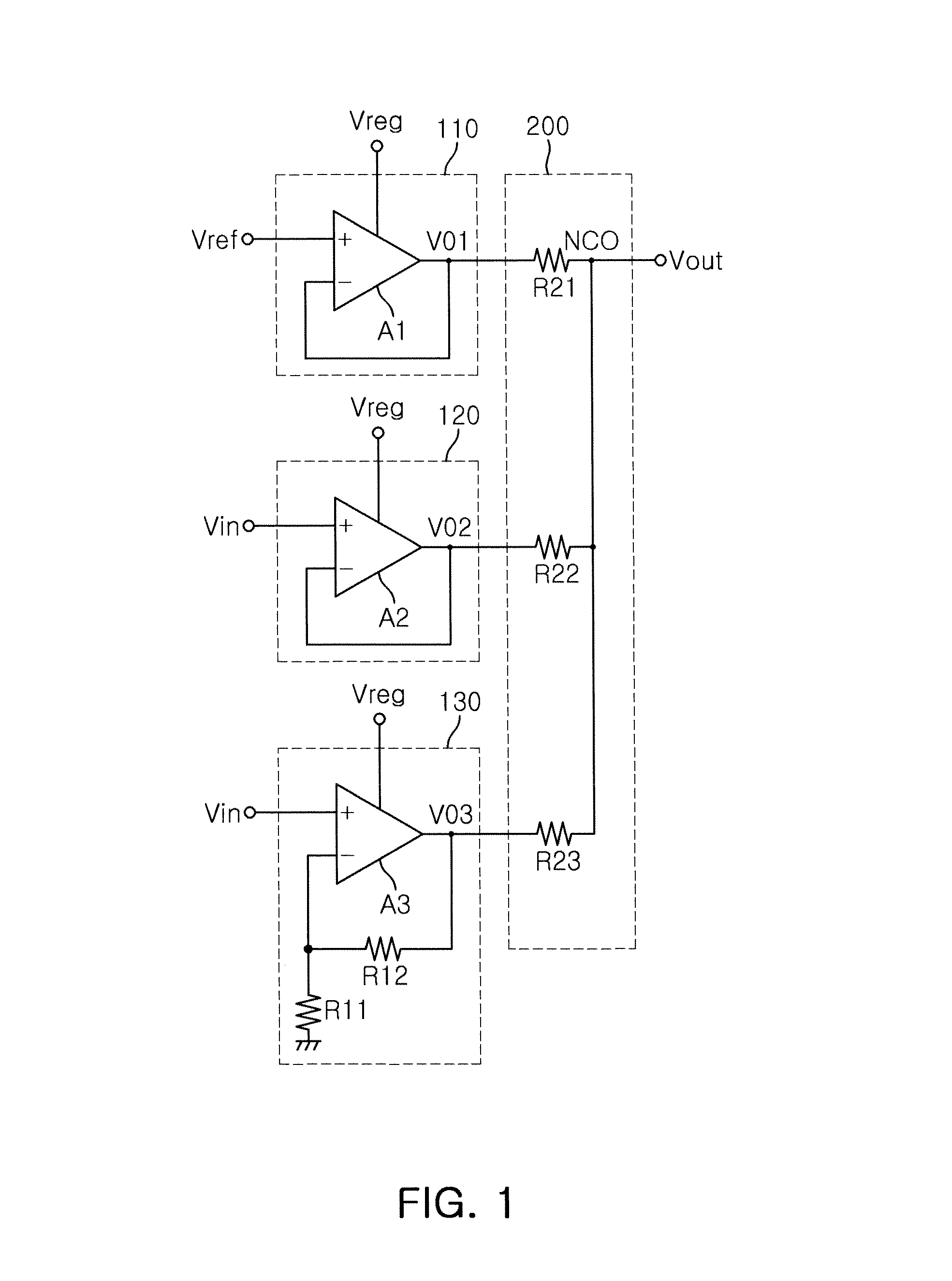
[0023]FIG. 1 is a circuit block diagram of a level shifter according to an embodiment of the present invention.

[0024]Referring to FIG. 1, the level shifter according to the embodiment of the present invention may include a first buffer amplifier 110, a second buffer amplifier 120, a positive feedback amplifier 130, and a level regulation unit 200. The first ...


PUM


Abstract

A level shifter includes: a first buffer amplifier transferring a preset reference voltage to a first output terminal; a second buffer amplifier connected in parallel to the first buffer amplifier and transferring an input voltage to a second output terminal; a positive feedback amplifier connected in parallel to the first buffer amplifier and the second buffer amplifier, and amplifying the input voltage by a preset gain to transfer the amplified input voltage to a third output terminal; and a level regulation unit regulating levels of output signals of the first buffer amplifier, the second buffer amplifier, and the positive feedback amplifier and providing the regulated output signals to a common output node.

Description

CROSS-REFERENCE TO RELATED APPLICATIONS[0001]This application claims the priority of Korean Patent Application No. 10-2010-0083606 filed on Aug. 27, 2010, in the Korean Intellectual Property Office, the disclosure of which is incorporated herein by reference.BACKGROUND OF THE INVENTION[0002]1. Field of the Invention[0003]The present invention relates to a level shifter which is applicable to a power amplification system, and more particularly, to a level shifter in which a plurality of amplifiers are connected in parallel, whereby a forward isolation spec of a power amplifier can be improved and the level shifter can be relatively scaled down.[0004]2. Description of the Related Art[0005]At present, a great deal of research has been conducted into a power amplifier (PA) using complementary-metal-oxide-semiconductor (CMOS) technology. A power amplifier includes a high frequency block which manages signal transmission and reception, and an analog control block which controls the power ...

Claims


Application Information

Patent Timeline
IPC IPC(8): H03L5/00
CPCH03K19/0175H03F2203/45138
Inventor HA, SANG HOONIIZUKA, SHINICHIKIM, YOUN SUKNA, JUN KYUNG
Owner SAMSUNG ELECTRO MECHANICS CO LTD
Why Eureka
Try Eureka