System and method for manufacturing a punch-out RFID transaction device

a technology of radio frequency operable and transaction devices, which is applied in the field of system and method for fabricating a radio frequency operable transaction device, can solve the problems of difficult or impossible replacement of payment means, affecting the user's experience, and affecting the user's ability to reuse the devi

Inactive Publication Date: 2010-11-02
LIBERTY PEAK VENTURES LLC
View PDF594 Cites 2 Cited by
  • Summary
  • Abstract
  • Description
  • Claims
  • Application Information

AI Technical Summary

Problems solved by technology

These payment means, however, were often difficult or impossible to replace if lost or stolen.
This is typically true, since these means of payment were disposable in that they were typically single-use devices, meaning that once the devices were used, the ability to reuse the devices was instantly lost to the user.
Initial transaction cards were typically restricted to select restaurants and hotels and were often limited to an exclusive class of individuals.
As the number of transaction cards issued increased, so did the administrative and security issues surrounding transaction card transactions.
While the advent of smart cards helped to alleviate some of the security issues surrounding transaction devices, smart cards did little to address fraud issues associated with a lost or stolen transaction card.
More particularly, while the identical size dimensions between the traditional transaction card and the smart card has the cost advantage associated with permitting a card manufacturer to manufacture smart cards on traditional transaction card fabrication machinery, the disadvantage is that the smart card users typically did little more to secure the smart card than what was done to secure a traditional transaction card.
For manufactures, however, the disadvantage is that since the key chain fobs may be irregular shape, the card manufacturer cannot typically use the same machinery to cut the fobs as the manufacturer used to cut the traditional cards and smart cards.
This, in turn, increases the manufactures transaction device fabrication costs.

Method used


Image

  • System and method for manufacturing a punch-out RFID transaction device
  • System and method for manufacturing a punch-out RFID transaction device
  • System and method for manufacturing a punch-out RFID transaction device

Examples


Embodiment Construction

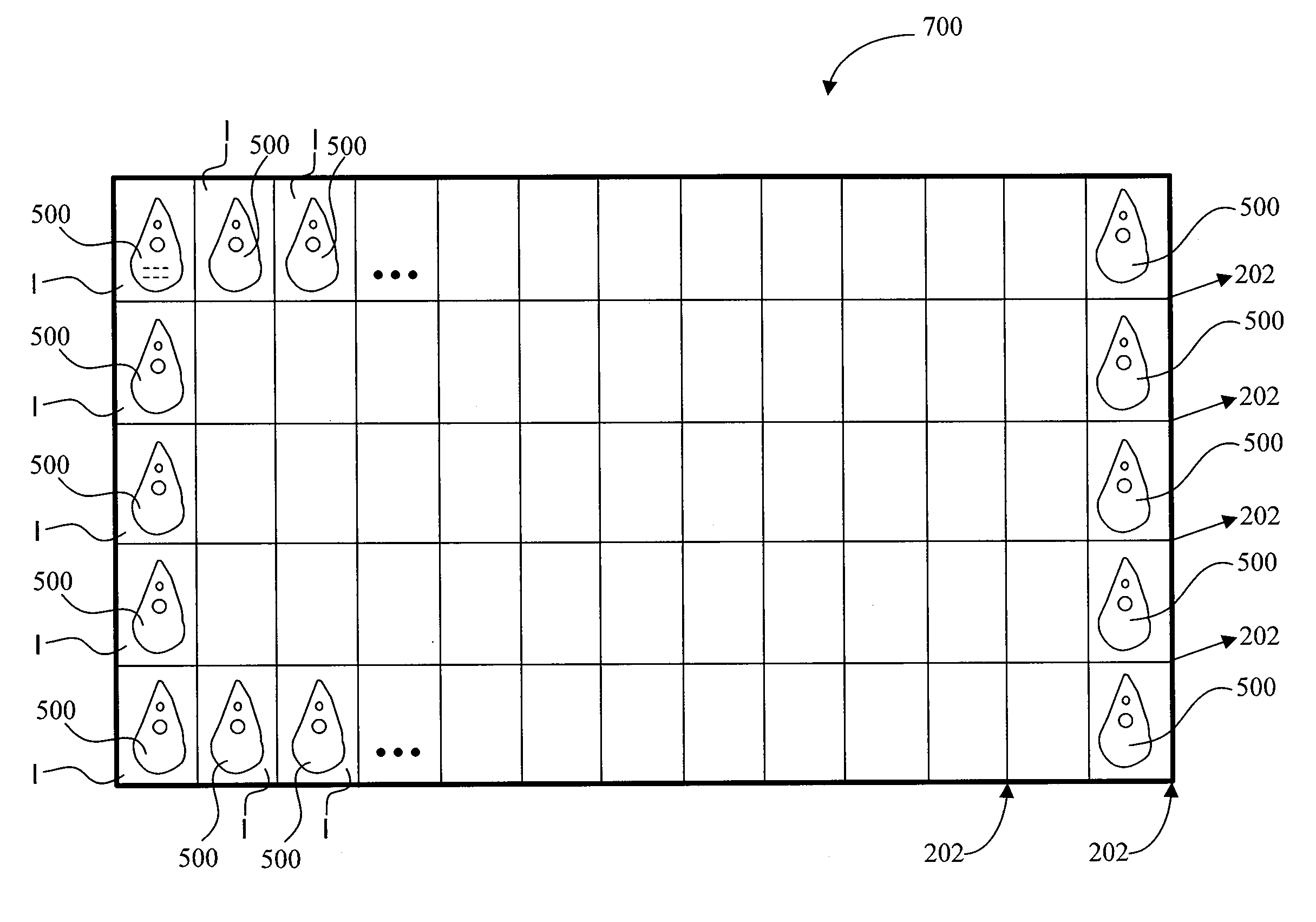
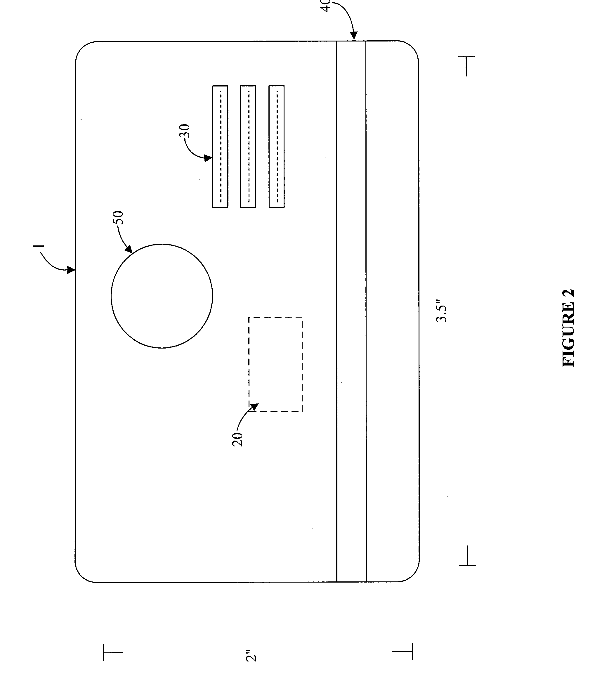
[0036]The present invention relates to contactless transaction devices and methods of making and using the same. Specifically, the present invention relates to a system and method for manufacturing a RFID transaction device using conventional transaction card manufacturing procedures. The present invention addresses the shortcomings in the prior art by providing a cost effective method for manufacturing irregular shaped RFID transaction device.

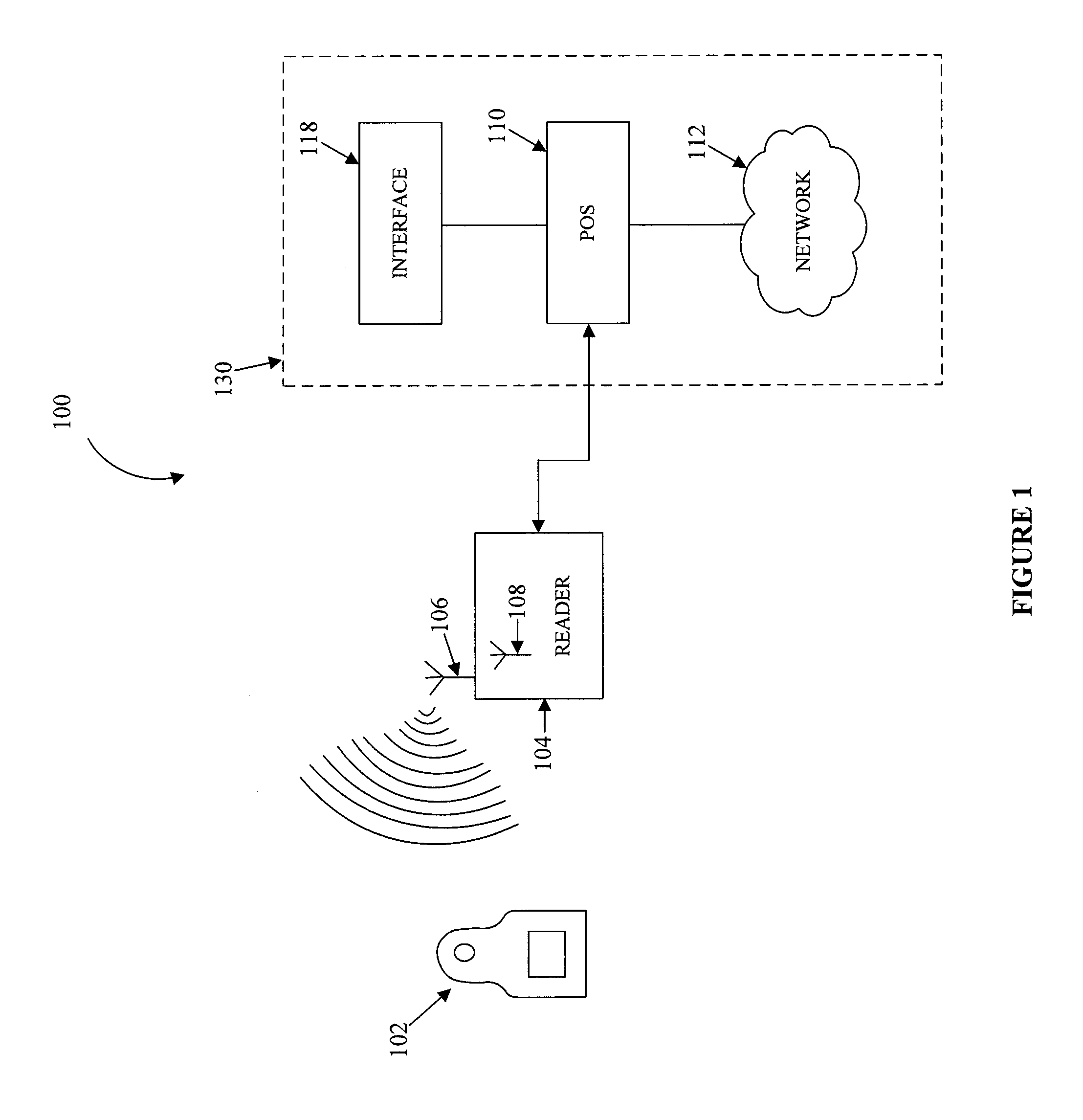
[0037]The transaction device in accordance with this invention may include means for conducting a transaction in a contactless environment. For example, the transaction device may include a RF operable transponder system, which may include a RF-based chip and antenna embedded therein. As used herein, the transponder system, antenna, and other internal transaction device circuitry supporting a RFID transaction may be called “RFID circuitry”.

[0038]The contactless transaction device can be utilized to efficiently conduct cashless transactions at,...


PUM

PropertyMeasurementUnit
thickaaaaaaaaaa
thickaaaaaaaaaa
pressureaaaaaaaaaa

Abstract

The present invention relates to a process for producing an irregularly shaped Radio Frequency operable transaction device using conventional International Standards Organization dimensions for conventional transaction cards. The invention provides for normal manufacture of a plurality of transaction cards joined together in a single sheet. The outline of a RFID transaction device is impressed in a center portion of one of the transaction cards. A RFID transaction device may then be removed, or punched out of the transaction card in accordance with the transaction device outline.

Description

RELATED APPLICATIONS[0001]This invention claims priority to U.S. patent application Ser. No. 10 / 192,488, entitled “SYSTEM AND METHOD FOR MD PAYMENT USING RADIO FREQUENCY IDENTIFICATION IN CONTACT AND CONTACTLESS TRANSACTIONS,” filed on Jul. 9, 2002 (which itself claims priority to U.S. Provisional Patent Application No. 60 / 304,216, entitled “SYSTEM AND METHOD FOR RFID PAYMENTS,” filed Jul. 10, 2001), to U.S. Provisional Patent Application No. 60 / 396,577, entitled “SYSTEM AND METHOD FOR PAYMENT USING RADIO FREQUENCY IDENTIFICATION IN CONTACT AND CONTACTLESS TRANSACTIONS” filed on Jul. 16, 2002, and to U.S. patent application Ser. No. 10 / 340,352, entitled “SYSTEM AND METHOD FOR INCENTING PAYMENT USING RADIO FREQUENCY IDENTIFICATION IN CONTACT AND CONTACTLESS TRANSACTIONS,” filed Jan. 10, 2003, all of which are incorporated herein by reference.FIELD OF INVENTION[0002]The present invention generally relates to transaction devices, and more particularly, to a system and method for fabric...

Claims


Application Information

Patent Timeline
Patent Type & Authority Patents(United States)
IPC IPC(8): G06Q30/00G06K7/00G06K19/02G06K19/07G06K19/077G06K19/08G06K19/16G06Q20/00
CPCG06K7/0008G06K19/02G06K19/0723G06K19/077G06K19/08G06K19/16G06Q20/00G06Q20/04G06Q20/10G06Q20/102G06Q20/105G06Q20/14G06Q20/20G06Q20/204G06Q20/327G06Q40/00Y10T83/141Y10T83/04
Inventor SAUNDERS, PETER D.
Owner LIBERTY PEAK VENTURES LLC
Why Eureka
Try Eureka