Eureka AIR delivers breakthrough ideas for toughest innovation challenges, trusted by R&D personnel around the world.

Method for designing an anterior curve of a contact lens

Active Publication Date: 2010-11-09
UNILENS CORP USA
View PDF24 Cites 20 Cited by
  • Summary
  • Abstract
  • Description
  • Claims
  • Application Information

AI Technical Summary

Problems solved by technology

The human eye frequently does not constitute a perfect optical system, but instead suffers from optical imaging errors which are known as ocular aberrations.

Method used


Image

  • Method for designing an anterior curve of a contact lens
  • Method for designing an anterior curve of a contact lens

Examples


Embodiment Construction

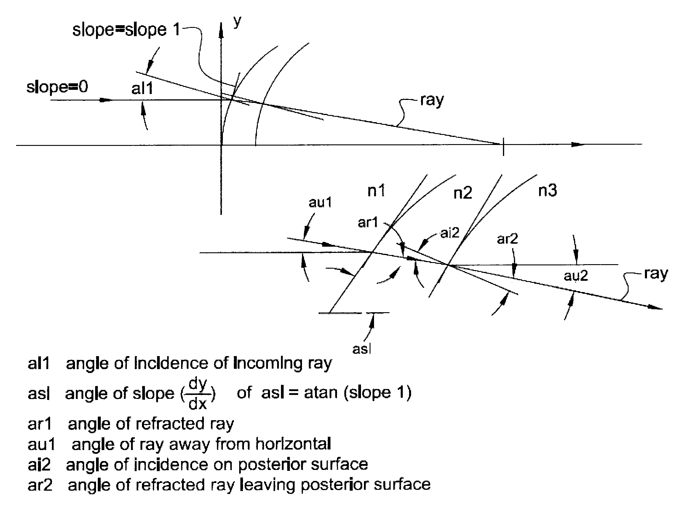
[0016]The contact lens design of the present invention allows for the control of the power from the center of the lens to the edge of the optic zone when the lens is placed on the eye. This control of the power is accomplished through ray tracing.

[0017]Specifically, the contact lens design is constructed with a lens system by using ray tracing. A ray of light is incident on a point on the anterior surface with a selected slope and proceeds through to the predefined posterior asphere. As the ray of light exits it will encounter a Null Lens described as follows:

[0018]A mathematically thin lens, that is a lens in which the anterior radius is virtually the same as the posterior radius and the lens thickness is virtually zero will have zero power and zero spherical aberration in air.

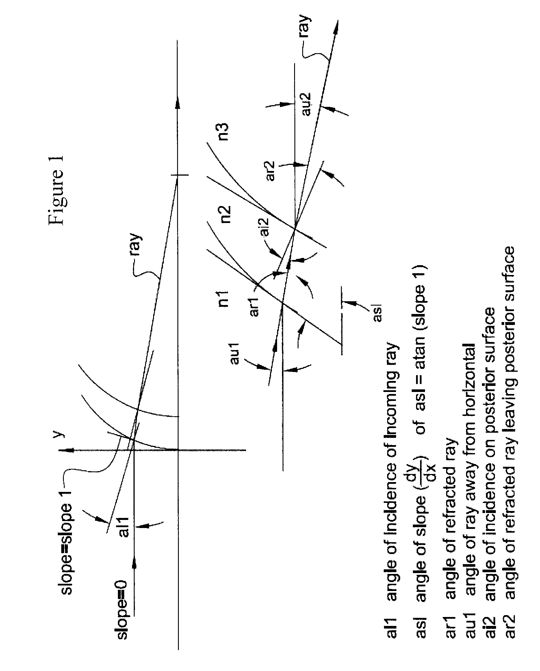
[0019]This null lens can be verified by examining the path of a horizontal ray of light that intersects the anterior surface of a contact lens as shown in FIG. 1.

[0020]The angle of incidence of the ray of lig...


PUM


Abstract

In accordance with the disclosure there is described herein a method of designing an anterior curve of a contact lens for the eye of a patient comprising the steps of providing a contact lens material having a posterior, a posterior curve having a predetermined asphericity, an anterior, an index of refraction and a center thickness; providing a geometry of a cornea, a distance power correction for the cornea and a near power correction for the cornea; determining a central distance power of the contact lens in air; calculating a central anterior radius of the contact lens using the posterior curve of the contact lens material, the index of refraction of the contact lens material, the center thickness of the contact lens material and the central distance power of the contact lens in air; calculating a center power of the contact lens on the eye of the patient using the index of refraction of tears at the posterior of the contact lens; and using an on-eye ray trace, said on-eye ray trace having a null lens compensation to create a targeted on-eye power profile.

Description

FIELD OF INVENTION[0001]The present invention generally relates to a method for designing a contact lens to provide an optimal corrective lens-eye system. More specifically, the present invention defines a method for designing an anterior curve of a contact lens for the eye using a null lens.BACKGROUND OF THE INVENTION[0002]Conventional contact lenses are generally designed to improve the visual acuity of the human eye. The human eye frequently does not constitute a perfect optical system, but instead suffers from optical imaging errors which are known as ocular aberrations.[0003]Ray tracing is one method of analyzing an optical system. It usually involves calculating parallel light rays entering an optical system and calculating the path of each ray of light. In some instances, the ray trace is included in the lens calculation to control the power profile of the lens.[0004]In the case of soft contact lenses, ray tracing can be used to control the power profile of a lens. This power...

Claims


Application Information

Patent Timeline
IPC IPC(8): G02C7/02
CPCG02C7/04G02C7/041G02C7/047
Inventor REHSE, DENIS
Owner UNILENS CORP USA
Why Eureka
Eureka Blog
Learn More