Naturally aspirated fluidic control for diverting strong pressure waves

a fluidic control and pressure wave technology, applied in the direction of intermittent jet plants, combustion types, turbine/propulsion engine ignition, etc., can solve the problems of preventing increasing the net thrust of pulse detonation devices, and hindering the propagation of pressure waves further upstream, etc., to achieve the effect of increasing the operational integrity and life of the system, reducing the risk of valving and high speed

Inactive Publication Date: 2010-11-09
GENERAL ELECTRIC CO
View PDF11 Cites 30 Cited by
  • Summary
  • Abstract
  • Description
  • Claims
  • Application Information

AI Technical Summary

Benefits of technology

[0005]In an embodiment of the present invention, the detonation chamber of a pulse detonation device is made up of a control region and a primary region. The upstream propagating pressure wave is split into these two regions. The control region is configured and structured such that the portion of the pressure wave entering the control region is accelerated ahead of the pressure wave propagating through the primary region. Further, the portion of the pressure wave passing through the control region is redirected and channeled so as to form a high speed flow which is directed into the backflow passing through the primary region. The mixing of these two flows impedes the progress of the backflow passing through the primary portion and redirects the flow, thus hindering the propagation of the pressure wave further upstream. By preventing the pressure wave from moving upstream within the device, reducing its size or magnitude and redirecting the flow, the operational integrity and life of the system is increased. Furthermore, this type of passive valving increases the net thrust of the pulse detonation device.

Problems solved by technology

The mixing of these two flows impedes the progress of the backflow passing through the primary portion and redirects the flow, thus hindering the propagation of the pressure wave further upstream.
Furthermore, this type of passive valving increases the net thrust of the pulse detonation device.

Method used


Image

  • Naturally aspirated fluidic control for diverting strong pressure waves
  • Naturally aspirated fluidic control for diverting strong pressure waves
  • Naturally aspirated fluidic control for diverting strong pressure waves

Examples


Embodiment Construction

[0011]The present invention will be explained in further detail by making reference to the accompanying drawings, which do not limit the scope of the invention in any way.

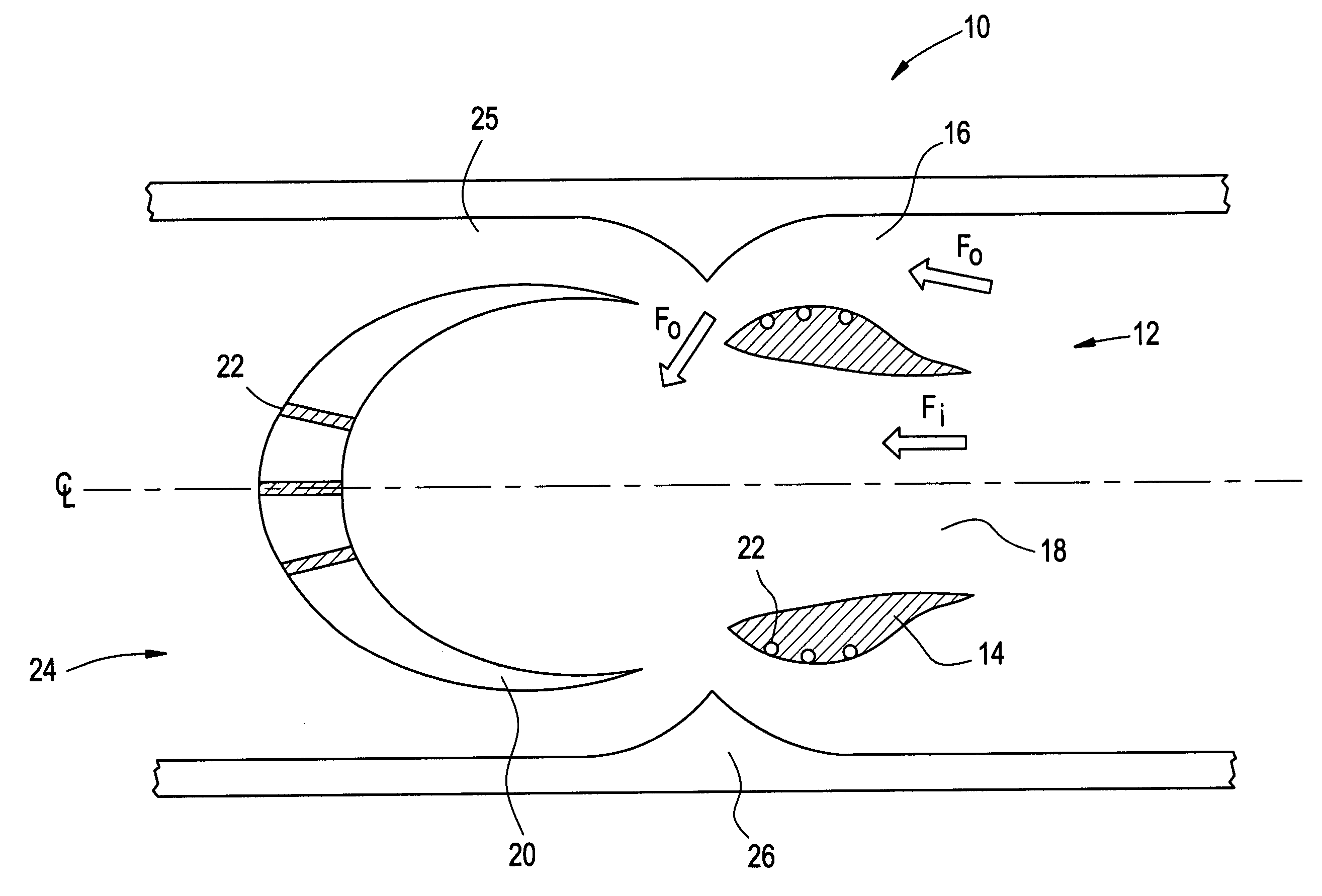
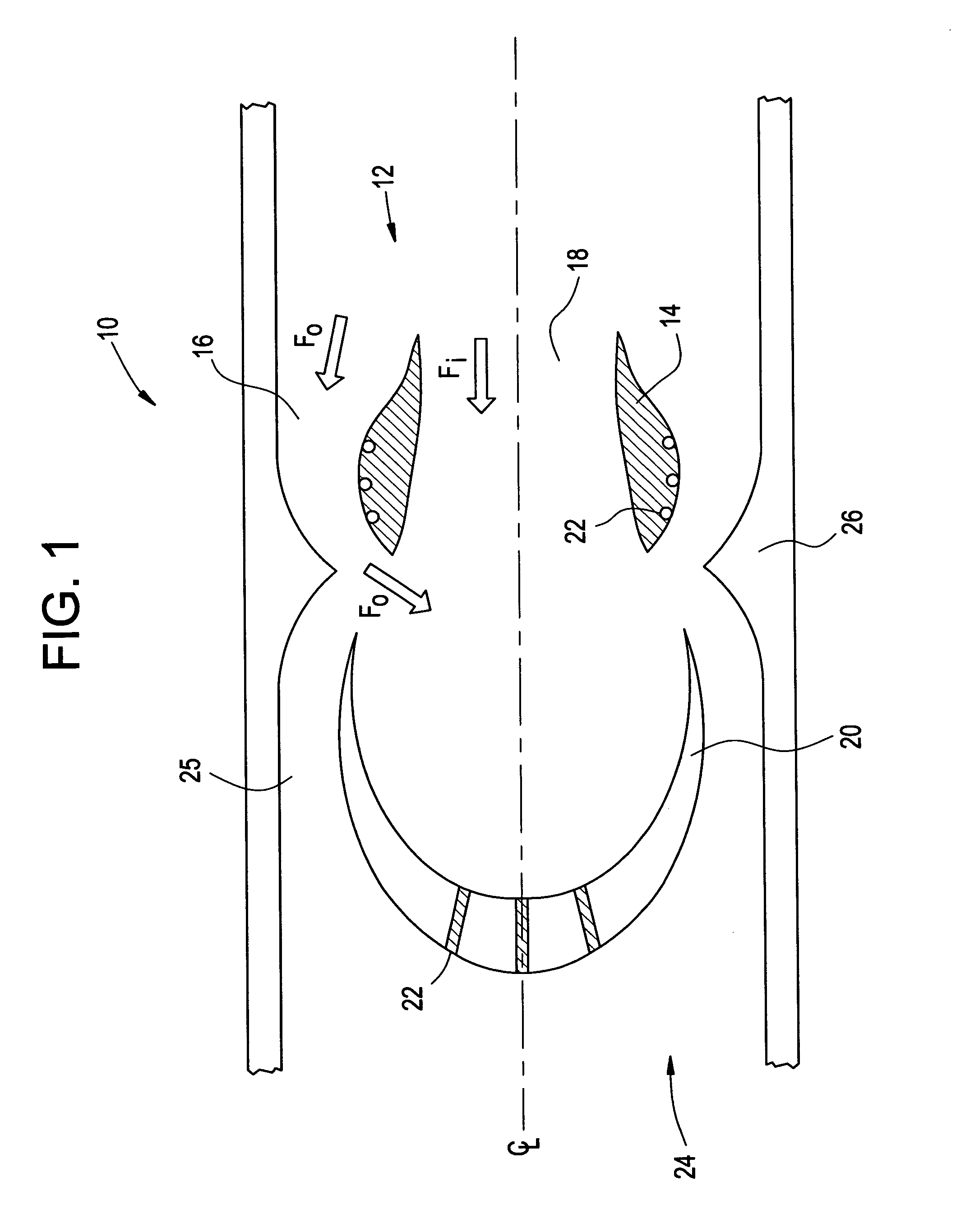
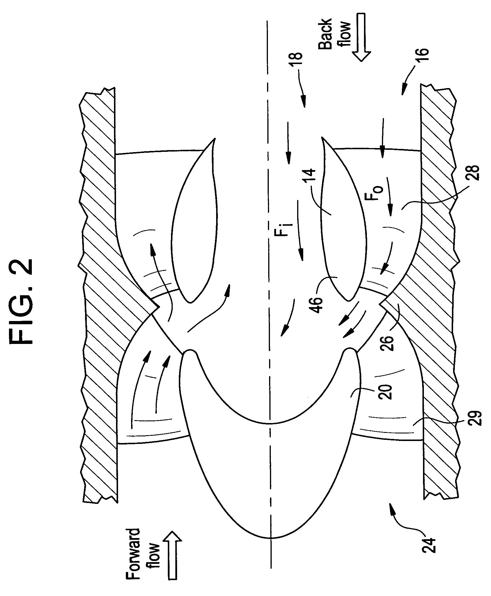
[0012]FIG. 1 is a cross-sectional side view of a portion of a pulse detonation device 10 including a fixed geometry flow separator 14, which divides a detonation chamber 12 of the device 10 into a primary region 18 and a control region 16. FIG. 2 is a cross-sectional side view of a portion of pulse detonation device 10, similar to the device 10 shown in FIG. 1, according to another embodiment of the invention. FIG. 3 is a cross-sectional side view of a portion of an alternative embodiment of pulse detonation device 30.

[0013]Turning now to FIG. 1, an exemplary embodiment of a pulse detonation device 10 is shown. Within the device 10 a fuel-air mixture is detonated in a detonation chamber 12, which is located downstream from both a fixed geometry flow separator 14 and an upstream chamber portion 20. As a result of th...


PUM


Abstract

A pulse detonation device for dividing a pulse detonation shock wave into an primary and control portion to reduce the strength of a propagating shock wave and / or change its direction. The device contains a flow separator which directs a portion of the shock wave into itself, thus reducing the shock wave's strength. In one configuration, the control region converges in cross-sectional area so as to accelerate the flow in the control region, while the primary region diverges to slow the flow in the primary region. The flow in the control region is directed, at an angle, into the flow of the primary region to impede and / or redirect the flow of the primary region.

Description

BACKGROUND OF THE INVENTION[0001]This invention relates to a passive apparatus which lessens the intensity of a back propagating pressure wave while having negligible impact on forward pressure loss.[0002]In existing pulse detonation devices a shock wave is produced as a result of each detonation. This shock wave propagates both downstream, producing thrust, and upstream toward the inlet of the device. The upstream propagation of these shock waves can have detrimental effects to the operation of a pulse detonation device. Specifically, in a valveless system, shock waves can enter the flow inlets, which feed air and / or fuel into the device, thus causing high pressure spikes in this structure, which can damage internal components or otherwise impede optimal operation.[0003]Several methods have been considered to prevent the propagation of strong pressure waves including mechanically valved systems. However, such systems require a number of moving parts, which increases the cost and co...

Claims


Application Information

Patent Timeline
Patent Type & Authority Patents(United States)
IPC IPC(8): F23D14/82
CPCF02K7/02F02K7/067
Inventor WIEDENHOEFER, JAMES FREDRICRASHEED, ADAMDEAN, ANTHONY JOHNPINARD, PIERRE FRANCOIS
Owner GENERAL ELECTRIC CO
Why Eureka
Try Eureka