Rapid disconnect system for cellular tower transmissions

a technology of cellular tower and transmission system, which is applied in the direction of antennas, antenna details, basic electric elements, etc., can solve the problems of not being able to use the available land, not being able to erect a support structure for a base station, etc., and achieves the effect of blocking further emission of rf energy and simple and quick methods

Inactive Publication Date: 2010-11-09
VINCULUMS SERVICES
View PDF3 Cites 8 Cited by
  • Summary
  • Abstract
  • Description
  • Claims
  • Application Information

AI Technical Summary

Benefits of technology

[0008]A disconnect system disables the radio frequency power coupled to cellular antennas mounted on a utility pole or other structure that supports non-cellular equipment. The disconnect system provides a simple and quick method for terminating transmissions by transceivers coupled to the cellular antennas to block further emission of RF energy by the cellular base station antennas. The disconnect system is mounted proximate the base of the support structure and is clearly labeled so that a utility worker having no experience or familiarity with the cellular transmission lines is able to disable the RF transmissions by the cellular antennas in one action and be assured that the cellular antennas are not emitting RF energy when the utility worker ascends the support structure to work in the vicinity of the cellular antennas. The antennas of a given cellular service provider on the support structure are disabled by operation of the disconnect system.

Problems solved by technology

Although the support structures for many base stations are specifically constructed to support the base station antennas, in many areas, particularly urban areas, a site may not be available to erect a support structure for a base station.
For example, an unused plot of land may not be available, the use of the available land may be restricted by ordinance, or the property owners in a desired location may not be willing to sell, lease or otherwise make the land available for a support structure.

Method used


Image

  • Rapid disconnect system for cellular tower transmissions
  • Rapid disconnect system for cellular tower transmissions
  • Rapid disconnect system for cellular tower transmissions

Examples


Embodiment Construction

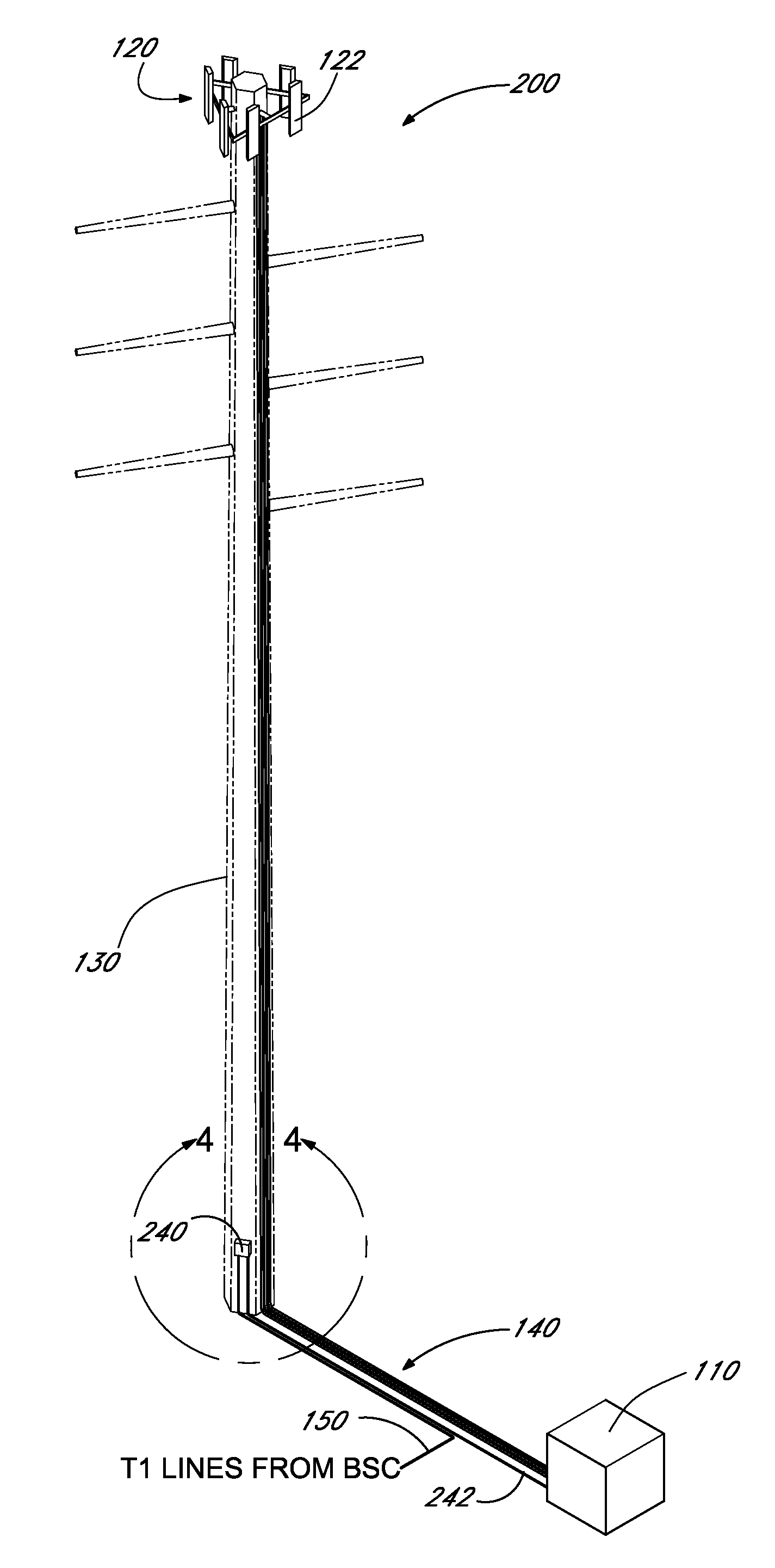
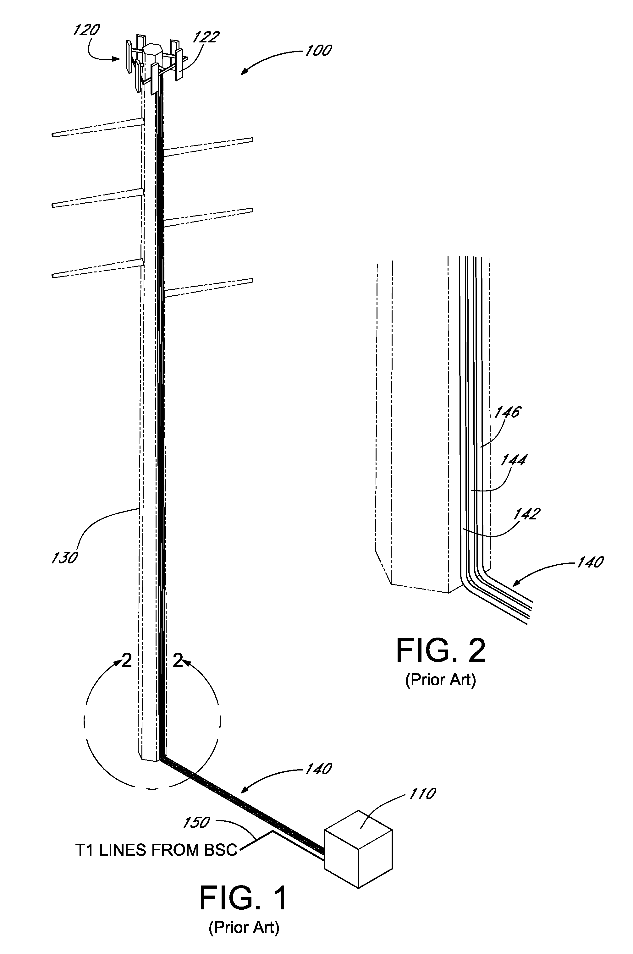
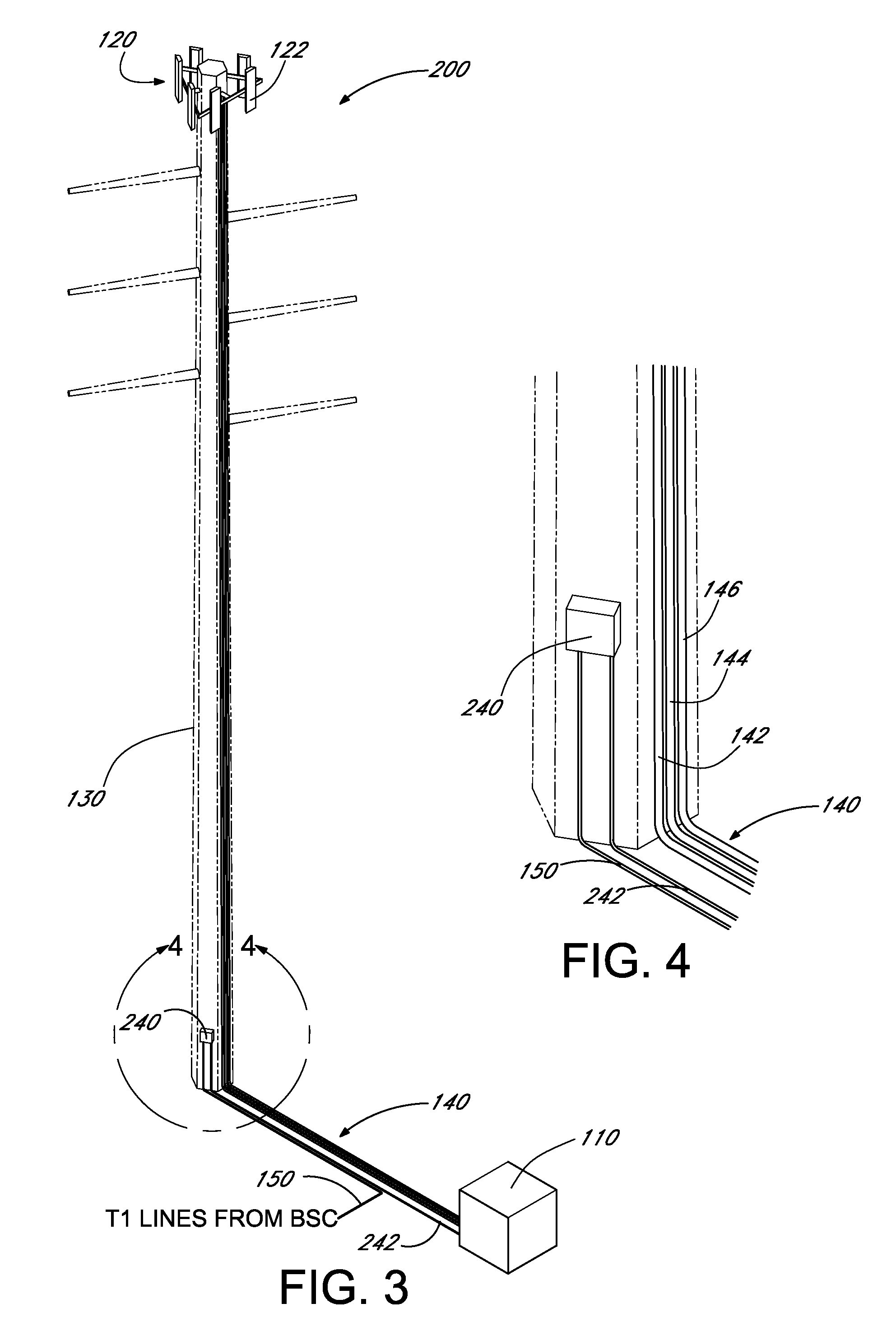
[0027]FIG. 1 illustrates a perspective view of an exemplary conventional cellular telephone base transceiver station (BTS) 100. The BTS comprises a weather-tight equipment housing 110, which encloses the base station electronics (not shown). The BTS further comprises an array 120 of cellular antennas 122, which are mounted to a top portion of a conventional utility pole (pylori) 130, and a coaxial cable assembly 140 that interconnects the cellular antennas to the electronics systems (not shown) within the equipment housing. As illustrated in the enlarged perspective view of FIG. 2, the cable assembly comprises a first radio frequency (RF) transmission cable 142, a second RF transmission cable 144 and a third RF transmission cable 144. More or fewer transmission cables may be included in a BTS in accordance with the number of antennas in the antenna array and in accordance with the number of antenna arrays on the utility pole.

[0028]As is well known in the field of cellular communicat...


PUM


Abstract

A safety disconnect system for a cellular antenna array on a support structure includes an enclosure mountable to a support structure. A fixed connector secured within the enclosure has contacts connected to conductors of at least a first digital data and control cable. A moveable connector within the enclosure includes corresponding contacts connected to conductors of a second digital data and control cable. The two connectors are selectively mated to engage the contacts of the two connectors. When the connectors are mated, transceivers within a base transceiver station (BTS) receive signals from a base station controller (BSC) and transmit RF energy via an array of antennas. A gripping handle secured to the moveable connector has a size and configuration selected to be grasped by a gloved hand to move the moveable connector away from the fixed connector in a rapid and safe manner to disable further transmissions by the transceivers.

Description

BACKGROUND OF THE INVENTION[0001]1. Field of the Invention[0002]The present invention is generally in the field of protective disconnect systems to terminate the transmission of RF power to cellular base station antennas mounted on power poles and other shared utility structures.[0003]2. Description of the Related Art[0004]The number of cellular telephones in the United States and in other countries is rapidly increasing. The increase in the number of cellular telephones in use has resulted in an increase in the number of cellular telephone base stations required to provide expanding coverage in previously unserved areas and to provide additional cells in many urban areas when the demand for cellular service exceeds the capacity of existing base stations. In general, a cellular base station comprises a mast, a tower or other support structure (e.g., a building) that supports one or more antennas a sufficient distance above the surface so that the antennas are able to transmit and re...

Claims


Application Information

Patent Timeline
Patent Type & Authority Patents(United States)
IPC IPC(8): H02H11/00
CPCH01Q1/002H01Q1/246
Inventor BOULGER, ANDREW D.
Owner VINCULUMS SERVICES
Why Eureka
Try Eureka