Automatic adjustment circuit for amplitude of differential signal
a technology of automatic adjustment and differential signal, applied in the direction of transmission, transmission monitoring, modulation, etc., can solve the problems of time and labor required for adjustment, inability to adjust the amplitude of differential signal itself, and inability to discriminate past results
- Summary
- Abstract
- Description
- Claims
- Application Information
AI Technical Summary
Benefits of technology
Problems solved by technology
Method used
Image
Examples
first embodiment
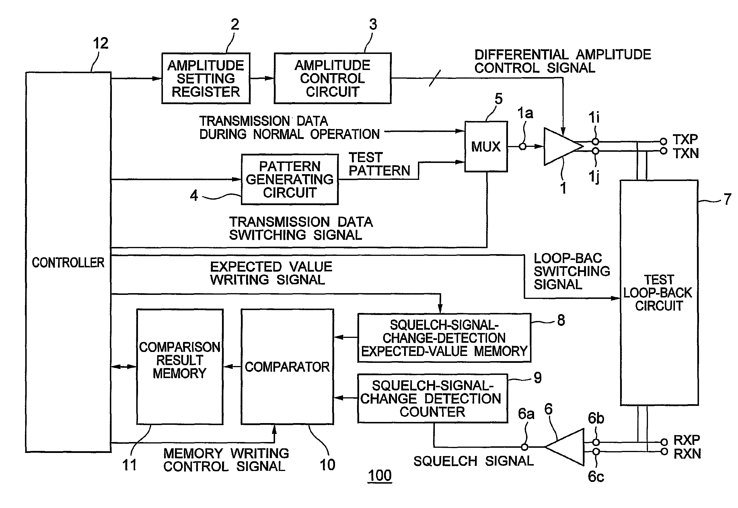
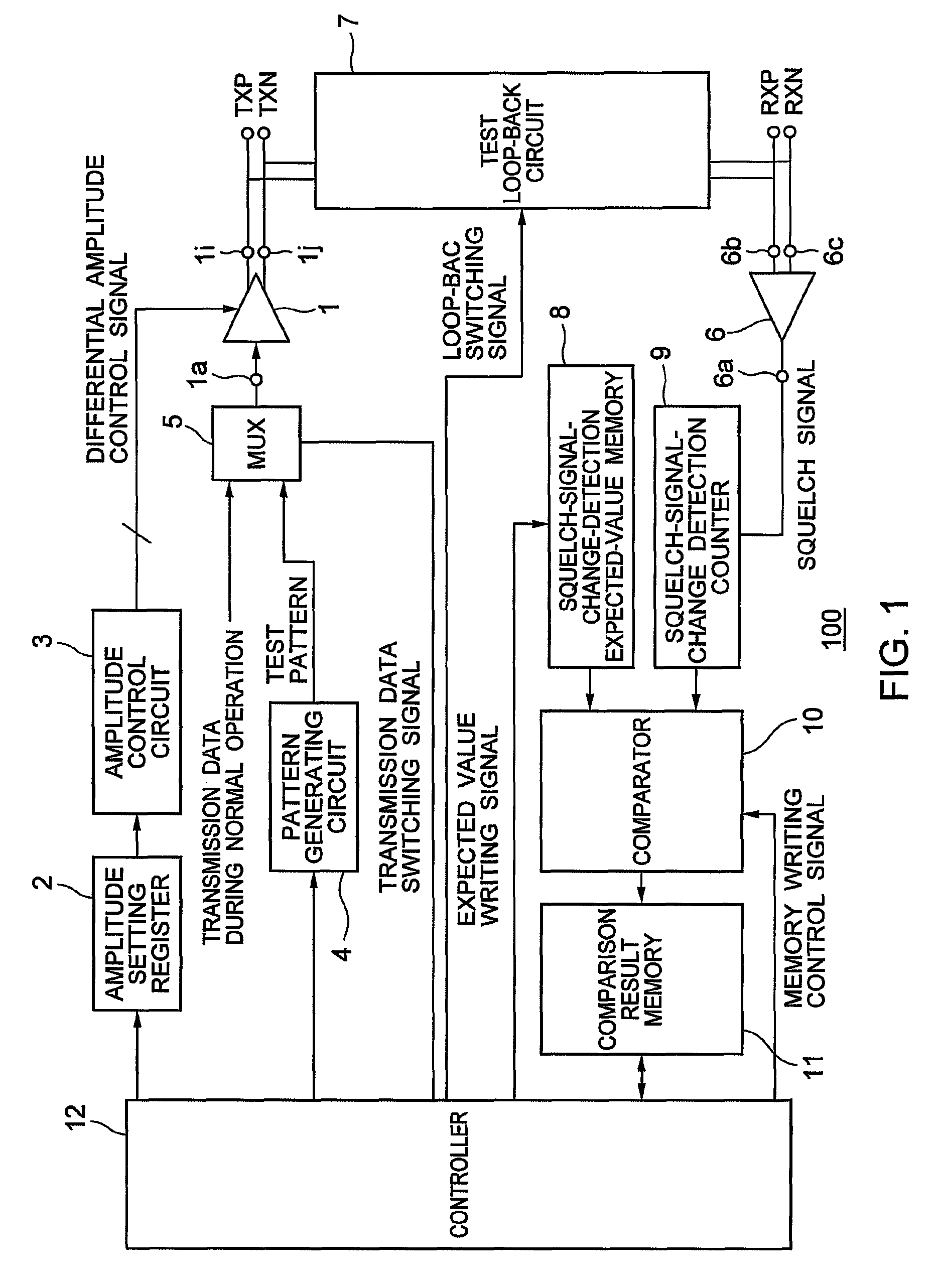
[0026]FIG. 1 is a block diagram showing an arrangement of a main part of an automatic adjustment circuit 100 for amplitude of differential signal according to a first embodiment of the present invention. In FIG. 1, circuits necessary for actual serial data transfer such as a differential signal receiver, which receives differential signals, are present other than those shown in the figure. However, for convenience of explanation, the circuits are not shown in the figure.
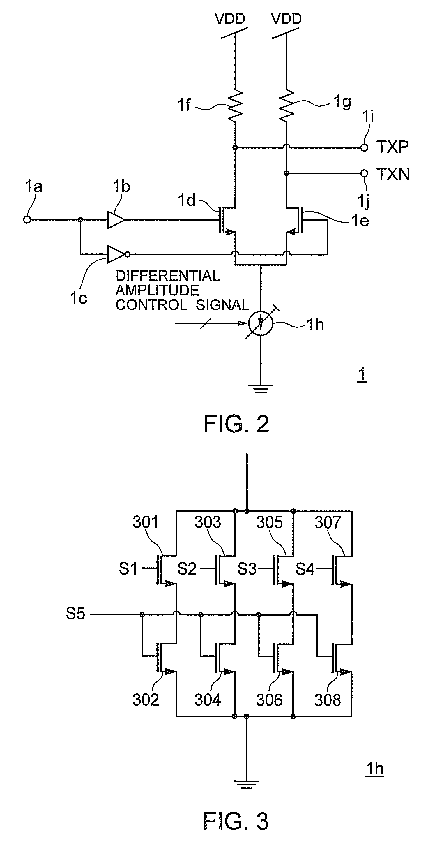
[0027]FIG. 2 is a circuit diagram showing an example of an arrangement of a differential signal transceiver of the automatic adjustment circuit 100 for amplitude of differential signal in FIG. 1. FIG. 3 is a circuit diagram showing an example of an arrangement of a variable current source of the differential signal transceiver in FIG. 2. FIG. 4 is a circuit diagram showing an example of an arrangement of a squelch detection receiver of the automatic adjustment circuit 100 for amplitude of differential signal in FIG. ...
second embodiment
[0088]In the first embodiment, the squelch detection receiver outputs a squelch signal on the basis of one squelch detection level.
[0089]In a second embodiment of the present invention, a squelch detection receiver outputs a squelch signal on the basis of plural squelch detection levels.
[0090]FIG. 7 is a block diagram showing an arrangement of a main part of an automatic adjustment circuit 200 for amplitude of differential signal according to the second embodiment. FIG. 8 is a circuit diagram showing an example of an arrangement of a squelch detection receiver of the automatic adjustment circuit 200 for amplitude of differential signal in FIG. 7.
[0091]Components denoted by reference numerals and signs same as those in the first embodiment are components same as those in the first embodiment.
[0092]As shown in FIG. 7, a squelch detection receiver 206 switches the squelch detection levels according to a squelch detection level switching signal outputted by the controller 12.
[0093]Compo...
PUM
 Abstract
Description
Claims
Application Information
 - R&D
- Intellectual Property
- Life Sciences
- Materials
- Tech Scout
- Unparalleled Data Quality
- Higher Quality Content
- 60% Fewer Hallucinations
Browse by: Latest US Patents, China's latest patents, Technical Efficacy Thesaurus, Application Domain, Technology Topic, Popular Technical Reports.
© 2025 PatSnap. All rights reserved.Legal|Privacy policy|Modern Slavery Act Transparency Statement|Sitemap|About US| Contact US: help@patsnap.com


