Radiant in-floor heating system

a radiant heating and in-floor heating technology, applied in the direction of fluid heaters, heating types, lighting and heating apparatus, etc., can solve the problem of lightweight panels, and achieve the effect of less strict tolerance, easy removal, and reduced installation heigh

Inactive Publication Date: 2010-11-16
KAYHART PANELS
View PDF81 Cites 16 Cited by
  • Summary
  • Abstract
  • Description
  • Claims
  • Application Information

AI Technical Summary

Benefits of technology

[0024]Another advantage of the present invention is that the tubing can snap into place within the panels. This is easily accomplished with the use of a rubber mallet or another suitable tool. The tubes can accordingly be snuggly held in place without the need for adhesives. Further, the tubes can be easily removed from the channels for repair or replacement.
[0025]A further advantage of the present invention is that an installer can see the top of the tubing during the installation process. Advantageously, the installer can then avoid the tubing when nails or the like are required to hold the flooring in place on the panels.
[0026]A still further advantage yet of the present invention is that the overall height of the installation is minimized. This is accomplished in part by elimination of an additional layer of material being installed over the panels and tubes.
[0027]A still further advantage yet of the present invention is that the system can be installed in any room regardless of whether the room below is finished.
[0028]A still further advantage yet of the present invention is that flares are located at the ends of the channels. The flares diverge left, right and vertically downward relative the longitudinal axis as the flare extends to the side of the panel. The vertical flare extends completely through the panel. The channels for receiving the tube terminate at the beginning of the flare, as the tubing is no longer restrained in the channel. The tubing is unrestrained in lateral movement in the flare, and is unrestrained vertically in one direction. Advantageously, the location of the panels can be held to a less strict tolerance during installation. The tubing is able to overcome a maximum offset amount between two panels without incurring undesirable sheer stress on the tube.

Problems solved by technology

Also, the panels are lightweight.

Method used


Image

  • Radiant in-floor heating system
  • Radiant in-floor heating system
  • Radiant in-floor heating system

Examples


Embodiment Construction

[0042]While the invention will be described in connection with several preferred embodiments, it will be understood that it is not intended to limit the invention to those embodiments. On the contrary, it is intended to cover all alternatives, modifications and equivalents as may be included within the spirit and scope of the invention as defined by the appended claims.

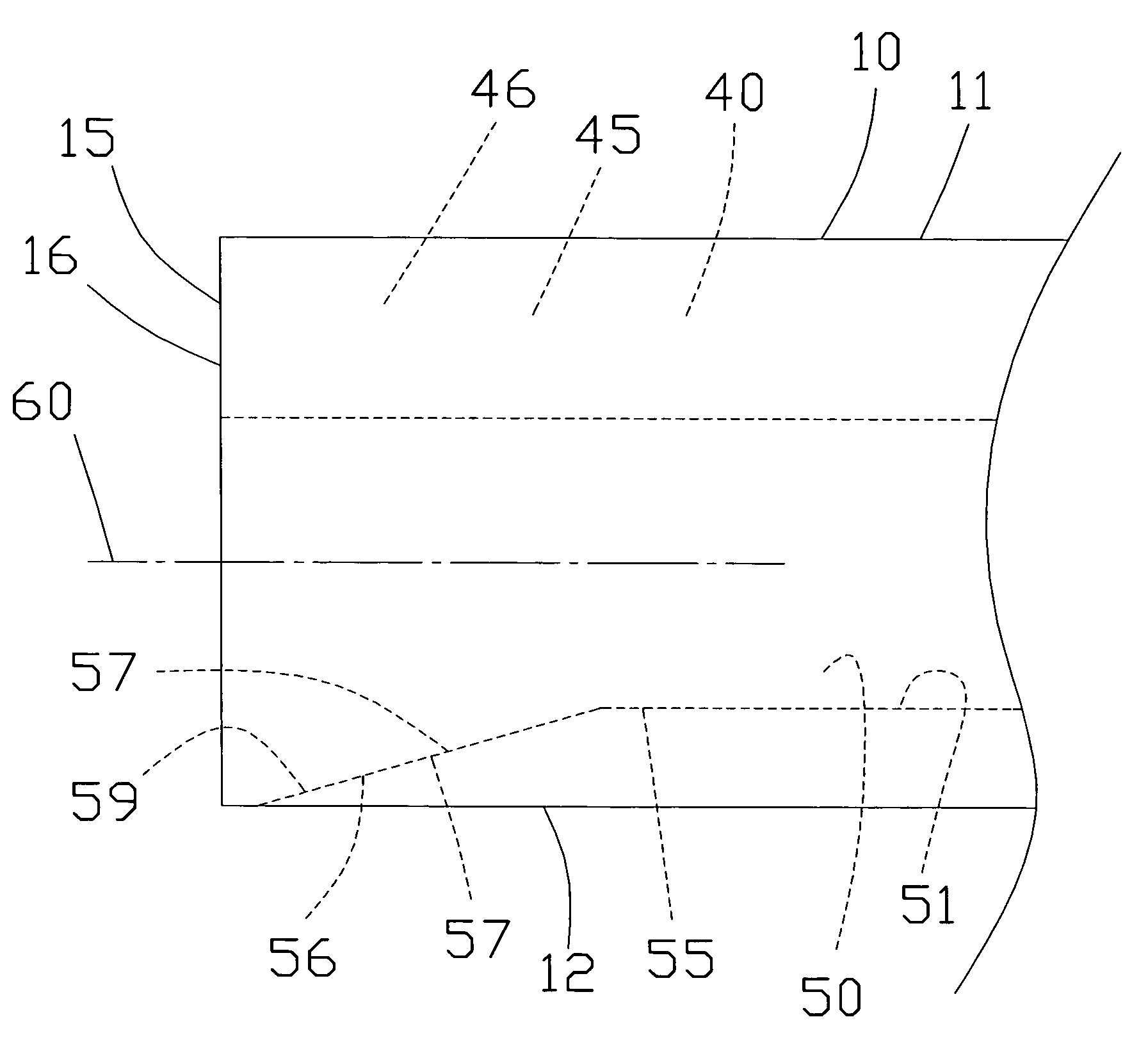
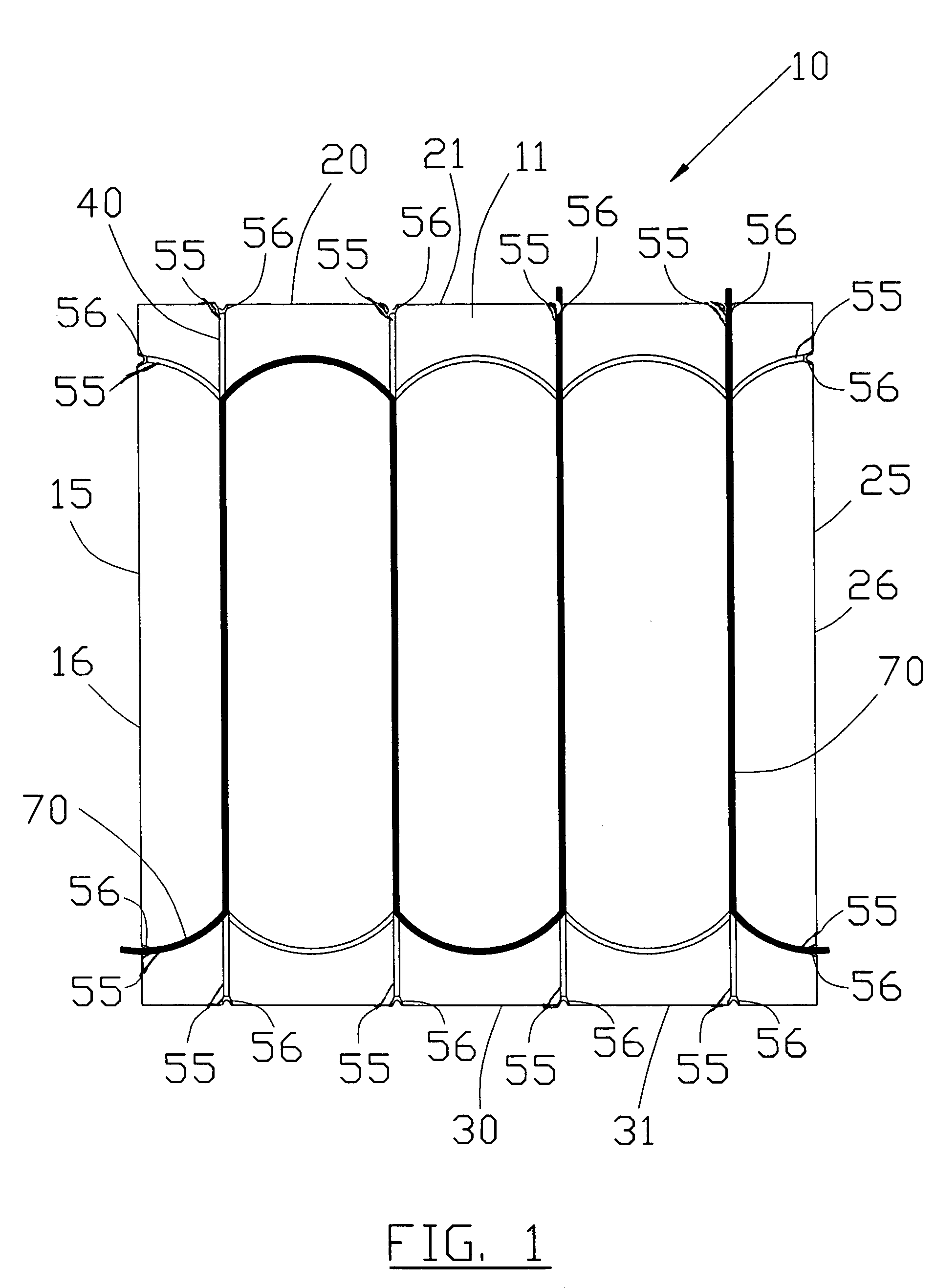
[0043]A preferred embodiment of the present invention comprises one or more panels 10 having one or more channels 40 formed therein. Tubing 70 can be inserted in the channels 40. Liquid 80 can be heated and pumped through the tubes 70 with a suitable heat pump.

[0044]Panels 10 are preferably comprised of a wooden board, such as particle board. One desirable quality of particle board is its insulative qualities. It is understood that other materials can be used without departing from the broad aspects of the present invention. Preferred dimensions of the panels are 4 feet in length and width. The panels are low profile ...


PUM


Abstract

The present invention relates to an in-floor radiant heating system having a tube that is received into low profile panels. Channels are formed in the top of the panels. The channels can have a neck shaped top section and a circular shaped bottom section. The bottom section has a diameter that is larger than the width of the top section. The diameter of the tubing is smaller than the diameter of the bottom section to ensure a snug fit. Flares can be located between the ends of the channels and the sides of the panel to allow the tube to bend and fit between adjacent panels that are offset up to a determined amount. A transition piece can be used to interface between a room with the in-floor system and one without. An installer can see the top of the tubing during the installation process.

Description

[0001]This application claims priority on US Provisional Application having application No. 60 / 811,219, filed on Jun. 6, 2006, the entire disclosure of which is hereby incorporated herein by reference.BACKGROUND OF THE INVENTION[0002]1. Field of the Invention[0003]The present invention relates to an in-floor radiant heating system having channels for receiving tubing wherein flares are provided at the ends of the channels to provide a channel alignment tolerance between the respective channels of adjacent panels.[0004]2. Description of the Related Art[0005]One common home heating method includes the use of forced-air furnaces. While these systems work well for their intended purposes, their use is not without some limitations. Forced-air systems work by distributing heated air into desired rooms. The heat has a tendency to quickly rise towards the ceiling, which is inefficient. Rooms, particularly those with tile or slate flooring, may feel cold. Rooms with hard wood flooring may al...

Claims


Application Information

Patent Timeline
Patent Type & Authority Patents(United States)
IPC IPC(8): E04C2/52
CPCE04F19/06F24D3/142F28F1/20Y02B30/00
Inventor KAYHART, PAUL H.
Owner KAYHART PANELS
Why Eureka
Try Eureka