Devices and methods for detecting rates of change of torque

a technology of torque and rate, applied in the field of sensors, can solve the problems of limited frequency response of the base torque signal, limited amplitude of variational torque measurable in the torque signal, and fundamentally limit the quality and frequency response of the signal in at least two ways

Active Publication Date: 2010-11-16
MAGCANICA
View PDF13 Cites 10 Cited by
  • Summary
  • Abstract
  • Description
  • Claims
  • Application Information

AI Technical Summary

Problems solved by technology

While ROC information can, in principle, be obtained by differentiating a torque dependent signal, such an approach would fundamentally limit signal quality and frequency response in at least two ways.
First, the frequency response of the base torque signal would be limited by the frequency response of the torque sensor system used.
Second, the amplitude of variational torque measurable in the torque signal would be limited due to electrical noise present in the torque sensor signal or be hidden within the resolution of the torque sensor signal.
Limitations of existing torque sensing technologies, such as frequency response limitations and the difficulty of obtaining an adequate resolution across the full range of torque measurement, have precluded their practical use for detecting rapid and / or small torque variations.
Moreover, direct measurement of ROC provides greater sensitivity to rapid and / or small torque variations, thereby exposing detail that could be lost in the frequency response or noise limitations of more complex and more costly torque sensors.
These include elastic torque sensor systems which measure strain by use of strain gauges or phase shift measurement by way of angular position sensors but whose frequency response is generally limited to approximately 1 kHz at best, making their usage for detecting torque transients rather limited.
Such systems have either limitations on the frequency response or sensitivity / resolution of the measurement of the pertinent magnetic property, limiting their ability to detect small but rapid variational torque components.

Method used


Image

  • Devices and methods for detecting rates of change of torque
  • Devices and methods for detecting rates of change of torque
  • Devices and methods for detecting rates of change of torque

Examples


Embodiment Construction

A. Introduction

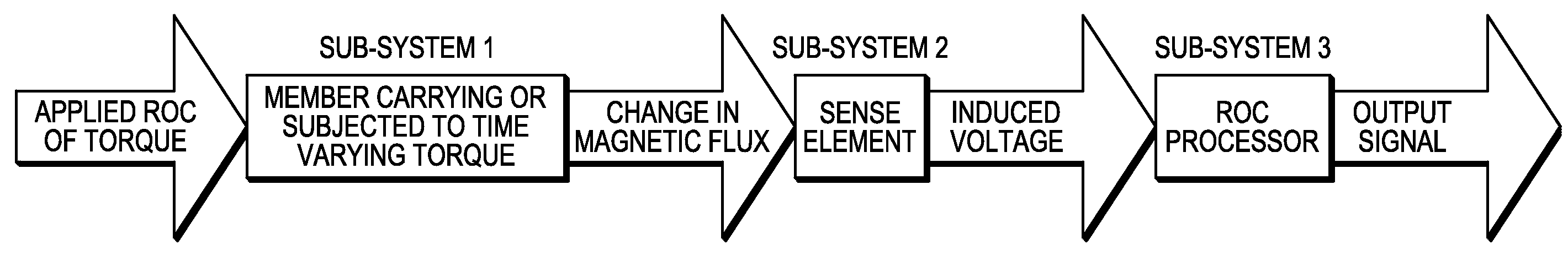
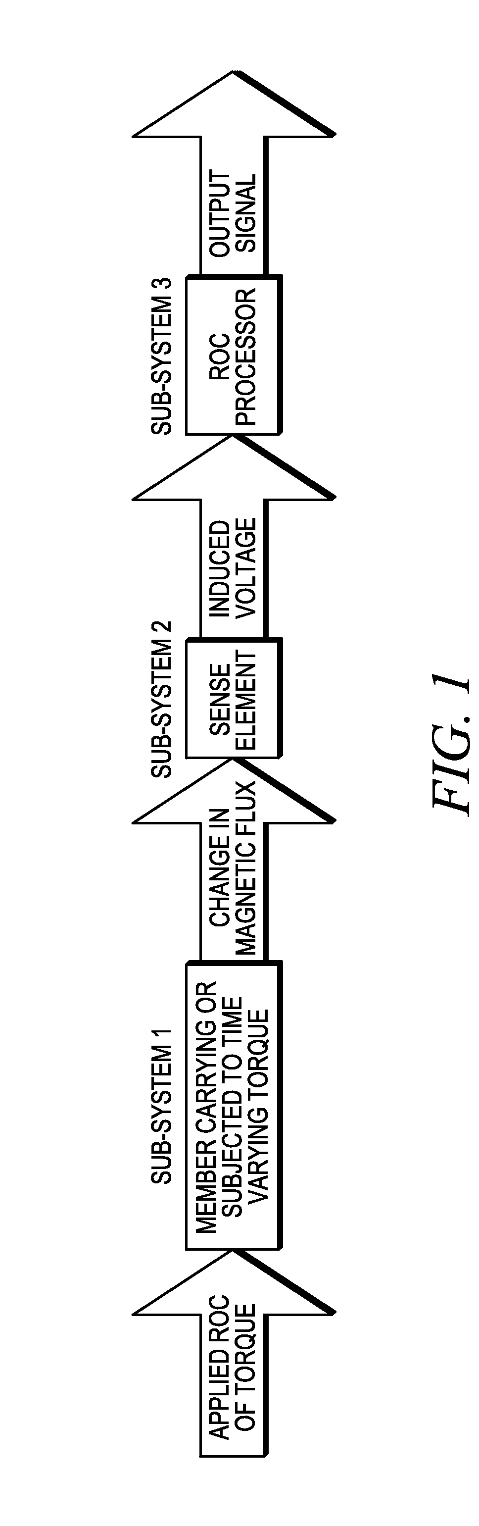
[0061]The invention is based on the discovery that rate of change of torque data can be obtained by monitoring changes in one or more magnetic parameters, which data can then be used for a variety of purposes. While not wishing to be bound by any particular theory, the ROC sensors of the invention are believed to have a magnetoelastic operational basis analogous to that reported for polarized band-type torque sensors. While the physical source of the signal is believed to be the same (i.e., the tilting of a circumferential magnetization towards a helical orientation in response to the stress anisotropy arising with the transmission of torque), ROC sensors respond to the time rate of change of magnetic flux associated with the varying torque, rather than the intensity of the magnetic field which arises in the encircling space. Referring first to FIG. 1, an applied rate of change of torque results, through a circularly magnetized magnetoelastic member carrying or subjec...


PUM

PropertyMeasurementUnit
frequency responseaaaaaaaaaa
frequencyaaaaaaaaaa
frequencyaaaaaaaaaa

Abstract

Sensors for outputting signals indicative of a rate of change of torque experienced by a magnetized member in response to a change in torque experienced by the member are described. Such sensors include at least one sense element capable of detecting a change in a magnetic parameter of a magnetized region of the member positioned proximate to the sense element in response to a change in torque applied to the member. Devices for detecting and / or measuring rates of changes in or of torque that employ one or more of these sensors are also described, as are various applications for such devices.

Description

RELATED APPLICATION[0001]This application claims the benefit of and priority to provisional application Ser. No. 60 / 883,780, filed on 6 Jan. 2007, the contents of which are herein incorporated by reference in their entirety for any and all purposes.FIELD OF THE INVENTION[0002]This invention concerns sensors capable of detecting rates of change in or of torque experienced by magnetized components, or portions of components, of various machines.BACKGROUND OF THE INVENTION1. Introduction[0003]The following description includes information that may be useful in understanding the present invention. It is not an admission that any such information is prior art, or relevant, to the presently claimed inventions, or that any publication specifically or implicitly referenced is prior art.2. Background[0004]Basic to the operation of modern machinery is the transmission of mechanical energy from source locations to points of utilization by means of rotating shafts transmitting torque. Beyond th...

Claims


Application Information

Patent Timeline
Patent Type & Authority Patents(United States)
IPC IPC(8): G01L3/00
CPCG01L3/102G01L3/103G01L3/104G01L3/101H02J7/0042
Inventor GARSHELIS, IVAN J.KARI, RYAN J.TOLLENS, STIJN P. L.
Owner MAGCANICA
Why Eureka
Try Eureka