Method and apparatus for laser processing

a laser processing and workpiece technology, applied in metal working equipment, manufacturing tools, welding/soldering/cutting articles, etc., can solve the problems of limiting the choice of laser processing system designers, limiting the selection of lasers, and limiting the laser removal rate of laser processing equipment, so as to improve the utilization rate of laser and optical components, the effect of improving the throughput of the apparatus employed

Inactive Publication Date: 2010-11-16
ELECTRO SCI IND INC
View PDF25 Cites 31 Cited by
  • Summary
  • Abstract
  • Description
  • Claims
  • Application Information

AI Technical Summary

Benefits of technology

[0038]Another advantage of the instant invention and embodied in this preferred embodiment is the elimination or reduction of laser settling time from the processing process. In the time line associated with the prior art illustrated in FIGS. 2 and 3, during the time periods associated with loading and aligning workpieces (20, 30, 32, 38, 40), the laser beam is not performing processing and is typically turned off to prolong the life of the laser oscillator, laser optics and other parts of the laser beam subsystem. Prior to beginning processing, the laser is turned back on and allowed to stabilize. The time period required for the laser to stabilize is referred to a settling time and can be a substantial fraction of the load and alignment time. In the apparatus and method disclosed herein, the laser does not have to be turned off between workpieces since the time between processing workpieces is limited to the amount of time the system takes to move the laser beam into the proper relationship with the workpiece and perform the final alignment of the laser beam to the workpiece. This time is typically a small fraction of the time required to load and align a workpiece and therefore does not require the laser to be shut off, thereby eliminating or reducing the settling time before beginning the processing of the next workpiece.

Problems solved by technology

Material removal rate for a laser processing apparatus is also limited by the per-pulse laser energy available and pulse repetition rate.
Selection of lasers, in terms of pulse energy available and pulse rate, is affected by technological advancement, cost, and other performance parameters which may limit the laser processing system designer's choice.
Several factors influence the choice of motion control components that determine the speed of laser beam positioning including cost, accuracy, power consumption and size.
Both the lasers and the power / energy detectors contribute to system overhead because they need time to stabilize after being turned on, thereby decreasing system throughput each time they are turned on.
Lasers are expensive components with useful lifetimes that are relatively limited and proportional to the length of time they are turned on.
Thus, lasers are typically turned off if they are to be idle for prolonged periods during system operations such as loading and unloading workpieces.
Although this apparatus can yield up to twice the throughput of a single station prior art apparatus, examination of the timing diagram in FIG. 3 still shows substantial system overhead devoted to loading and unloading workpieces.
This approach suffers from the increased cost and complexity of adding an additional laser and the optical and mechanical components required to direct the laser beam to the workpiece, but still does not avoid the processing time delays associated with turning on and stabilizing the lasers.

Method used


Image

  • Method and apparatus for laser processing
  • Method and apparatus for laser processing
  • Method and apparatus for laser processing

Examples


Embodiment Construction

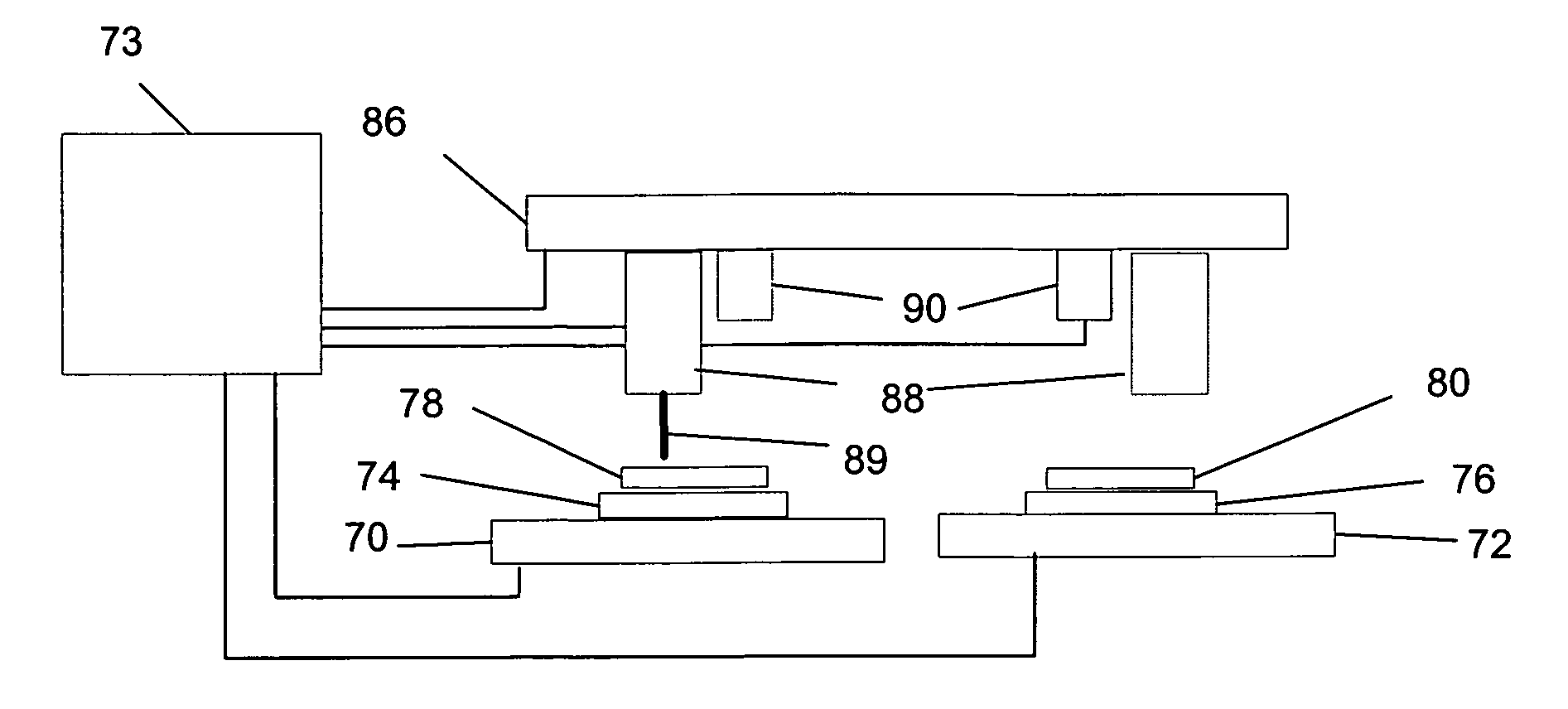
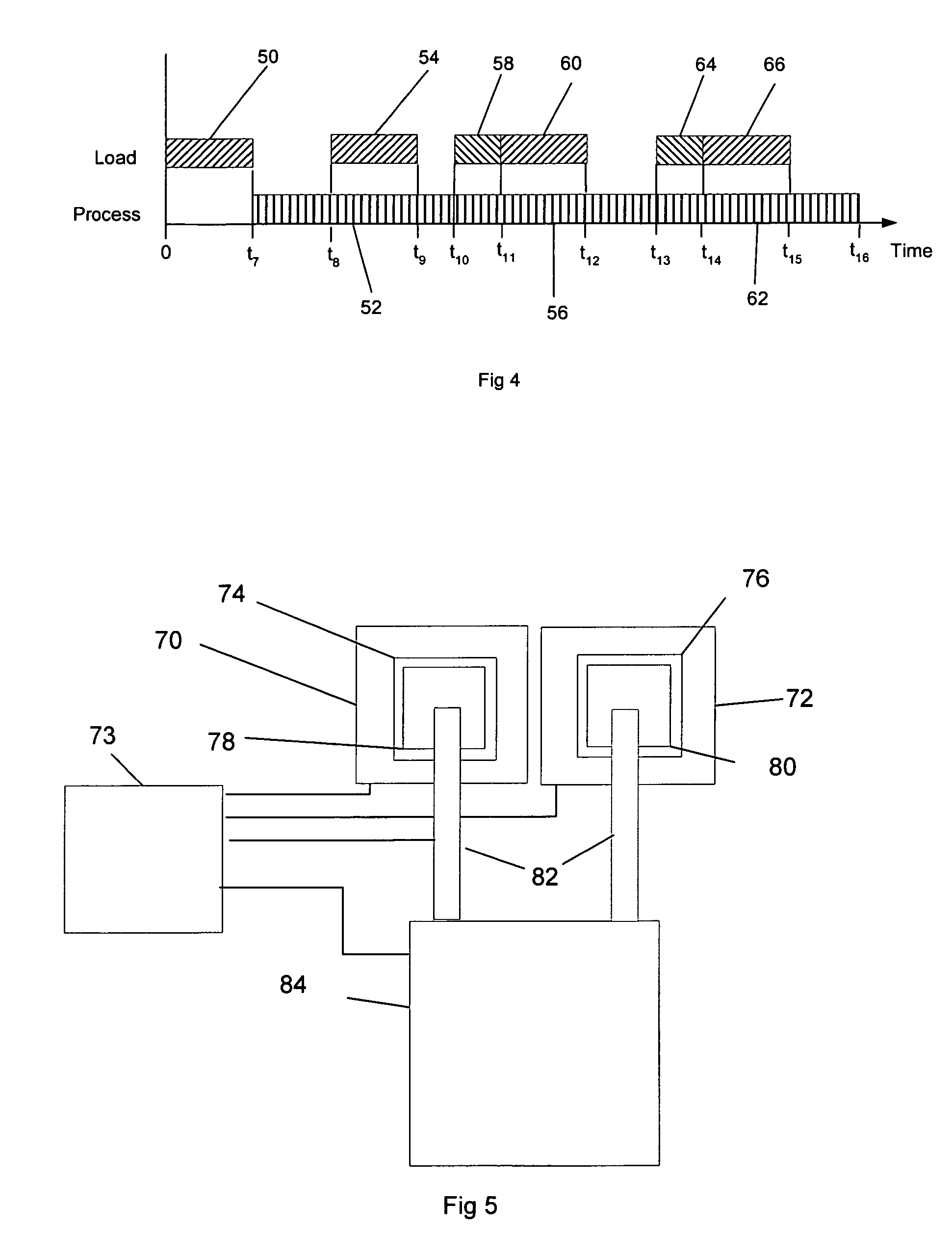
[0025]FIG. 5 is a simplified partial schematic diagram of a plan view of a preferred embodiment of the present invention comprising two X, Y tables 70, 72 holding two stages 74, 76 each of which can hold workpieces 78, 80, respectively. The X, Y tables 70, 72 are independently controlled by a controller 73, which may be a computer and which controls the operation of the various parts which comprise a preferred apparatus. The workpieces 78, 80 are loaded and unloaded from stages 74, 76 by load arm 82, which can move workpieces from either station to and from autoloader 84. The solid lines show load arm 82 positioned to load or unload workpiece 78 to or from stage 74 and the dotted lines show load arm 82 positioned to load or unload workpiece 80 to or from stage 76. Autoloader 84 is a device that holds multiple workpieces and, under control of controller 73 provides unprocessed workpieces to load arm 82 for transport to stages 74, 76 or accepts processed workpieces from load arm 82 fo...


PUM

PropertyMeasurementUnit
thicknessesaaaaaaaaaa

Abstract

A method and an apparatus for processing workpieces with a laser beam include first and second stages for holding the workpieces and first and second laser beam paths. The first workpiece is loaded upon the first stage, aligned with the first laser beam path, and processing begun. While the first workpiece is aligned in relation to the first laser beam path, the second workpiece is prepared in relation to the second laser beam path. Processing of the second workpiece is begun as soon as the laser beam is available for processing.

Description

TECHNICAL FIELD[0001]Generally, the present invention relates to laser processing a workpiece. Particularly it relates to laser processing apparatus which provides at least two substantially independent workpiece holders. More particularly it relates to laser processing apparatus able to manipulate at least two substantially independent workpiece holders which allow two or more workpieces to go through different processing steps simultaneously. Processing steps may include loading, aligning, micromachining, inspection or unloading a workpiece. The present invention allows for the micromachining of one or more workpieces while one or more additional workpieces are going through other processing steps without substantially altering or delaying overall processing.BACKGROUND OF THE INVENTION[0002]Laser processing is employed on a variety of electronic devices to achieve a variety of effects. Typically electronic devices appear at various stages of their manufacture as substantially plan...

Claims


Application Information

Patent Timeline
Patent Type & Authority Patents(United States)
IPC IPC(8): B23K26/38B23K26/08B23K26/03
CPCB23K26/0673B23K26/026B23K26/422H01L21/481H05K3/0026B23K26/041B23K26/4075B23K2201/40H01L2224/82039H01L2924/01046H01L2924/01077H01L2924/01078H01L2924/01079H01L2924/09701H05K3/0008H05K3/0097H01L2924/01067H01L2924/01068B23K26/035B23K26/042B23K26/702B23K26/40B23K2101/40B23K2103/50H01L21/324H01L21/477
Inventor WILE, DONALD E.JOHANSEN, BRIAN C.
Owner ELECTRO SCI IND INC
Why Eureka
Try Eureka