Starter
a technology of starter and motor, which is applied in the direction of engine starter, machine/engine, electric generator control, etc., can solve the problems of increasing the total manufacturing cost of the starter, increasing the number of starters, and difficulty in maintaining an adequate contact area between the movable contact and the motor side conta
- Summary
- Abstract
- Description
- Claims
- Application Information
AI Technical Summary
Benefits of technology
Problems solved by technology
Method used
Image
Examples
first embodiment
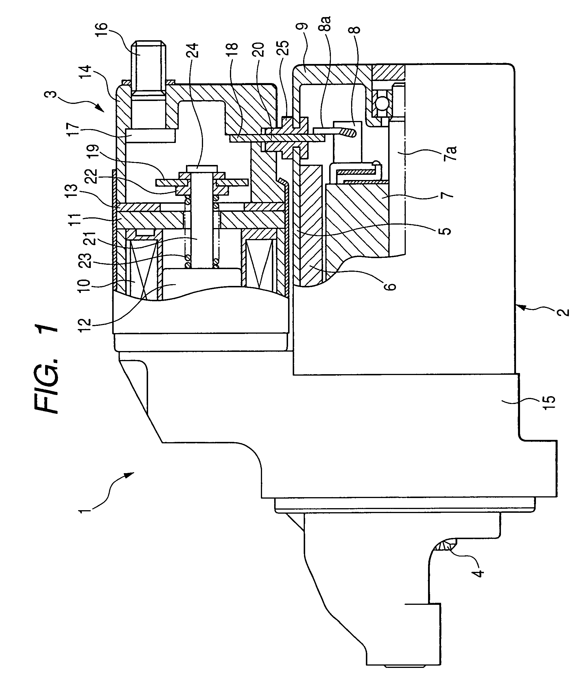
[0030]A description will be given of a starter 1 according to a first embodiment of the present invention with reference to FIG. 1 and FIG. 2.
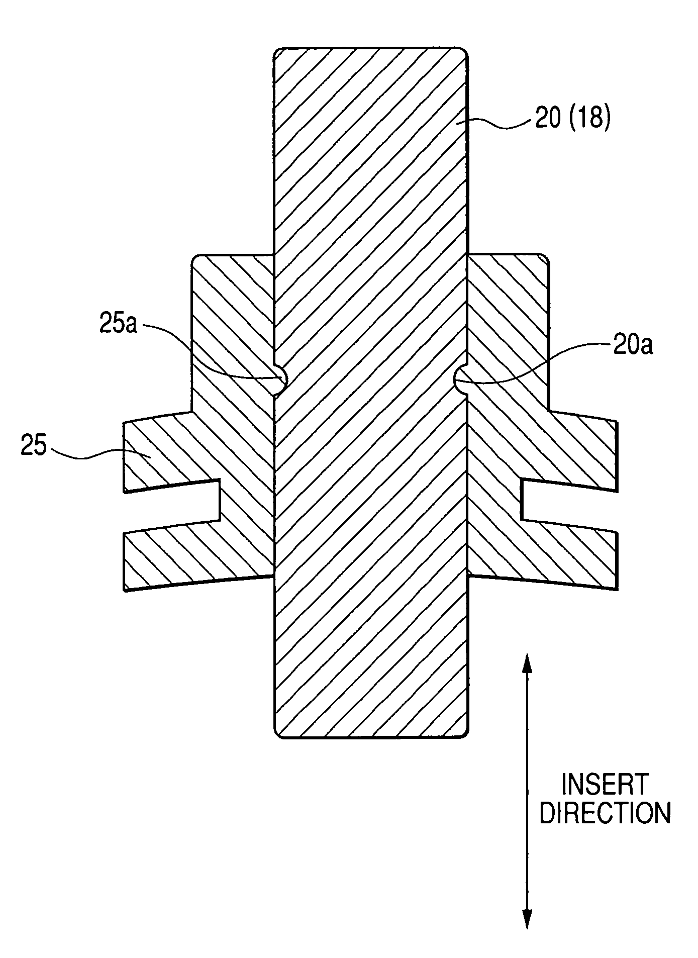
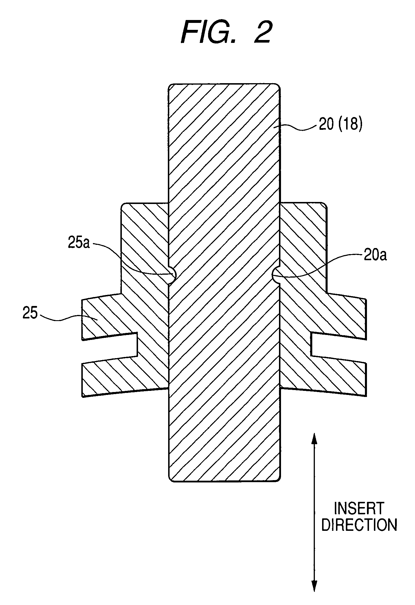
[0031]FIG. 1 is a schematic perspective diagram showing an entire configuration of the starter 1 according to the present invention. In particular, FIG. 1 shows a cross section of main components of the starter 1. FIG. 2 is a cross sectional view of a positioning mechanism for positioning a M terminal plate 20 in a grommet 25 in the starter 1 according to the first embodiment.
[0032]The starter 1 has a starter motor 2, an electromagnetic switch 3 for opening / closing a main contact placed in a motor circuit of the starter motor 2, a pinion gear 4 rotating on-receiving a drive torque transmitted form the starter motor 2, and the like. The operation and configuration of the main contact will be explained in detail later. On engaging the pinion gear 4 to a link gear (not shown), the operation of an internal combustion engine (not shown) of a vehicl...
second embodiment
[0049]A description will be given of the starter according to the second embodiment of the present invention with reference to FIG. 3A and FIG. 3B.
[0050]FIG. 3A is a side view of the positioning mechanism for positioning the M terminal plate in the grommet in the starter according to the second embodiment. FIG. 3B is a sectional view along A-A line shown in FIG. 3A.
[0051]The M terminal plate 20 in the starter 1 according to the second embodiment of the present invention has a thick part 20b at the other end side where the M contact 18 is formed. As shown in FIG. 3B, the thick part 20b is thicker than a thickness of the inserting part of the M terminal plate 20. A step part between the thick part 20b and the inserting part is contacted to the upper surface of the grommet 25 so as to pass the M terminal plate 20 shown in FIG. 3B toward the bottom direction shown in FIG. 3B through the penetration hole.
[0052]The pig-tail 8a of the positive electrode brush 8 is fixed to one end part of ...
third embodiment
[0054]A description will be given of the starter according to the third embodiment of the present invention with reference to FIG. 4.
[0055]FIG. 4 is a side view of the positioning mechanism for positioning the M terminal plate 20 in the grommet 25 in the starter according to the third embodiment.
[0056]The M terminal plate 20 in the starter 1 according to the third embodiment has a wide width part 20c at the other end part of the M terminal plate 20 where the M contact 18 is formed. As shown in FIG. 4, the wide width part 20c is larger than a width (toward the horizontal direction in FIG. 4) of the inserting part to be inserted into the penetration hole. The step part formed between the wide width part 20c and the inserting part is contacted to the upper end surface of the grommet 25. This configuration can prevent the M terminal plate from falling down toward the bottom in FIG. 4 through the penetration hole.
[0057]The pig-tail 8a of the positive electrode brush 8 is fixed to one end...
PUM
 Abstract
Description
Claims
Application Information
 - R&D
- Intellectual Property
- Life Sciences
- Materials
- Tech Scout
- Unparalleled Data Quality
- Higher Quality Content
- 60% Fewer Hallucinations
Browse by: Latest US Patents, China's latest patents, Technical Efficacy Thesaurus, Application Domain, Technology Topic, Popular Technical Reports.
© 2025 PatSnap. All rights reserved.Legal|Privacy policy|Modern Slavery Act Transparency Statement|Sitemap|About US| Contact US: help@patsnap.com


