Speed reducer, robot, and robot hand

a technology of speed reducer and speed reduction, which is applied in the direction of arms, manufacturing tools, and gears. it can solve the problems of large backlash, inability to use the power obtained from a power source such as a motor, and large backlash as a whole, so as to reduce the speed of an output of a motor and increase the torque output of the motor. , the effect of high torque outpu

Inactive Publication Date: 2012-12-27
SEIKO EPSON CORP
View PDF11 Cites 7 Cited by
  • Summary
  • Abstract
  • Description
  • Claims
  • Application Information

AI Technical Summary

Benefits of technology

[0012]Between the through hole and the through pin, the elastic section is placed, and the elastic section makes contact with the through hole and the through pin. In addition, the elastic section urges, or is biased against, the through pin and the through hole. Therefore, when the revolving gear rotates, the elastic section is deformed, and the torque of the revolving gear is transferred to the through pin. When the direction of rotation of the revolving gear is switched, the amount of deformation of the elastic section is changed in response to changes in the torque of the revolving gear. As a result, since a state in which the through hole and the through pin make contact with each other with the elastic section sandwiched between the through hole and the through pin is maintained, it is possible to prevent or avoid the occurrence of backlash between the through hole and the through pin.
[0038]According to this application example, the electronic apparatus has the motor, the speed reducer, and the movable portion. The speed reducer reduces the speed of an output of the motor. This makes it possible to increase the torque which is output from the motor. In addition, it is possible to operate the movable portion by using the high torque output. The speed reducer is any of the speed reducers described in the above-mentioned application examples. Therefore, in the speed reducer, the occurrence of backlash between the through pin and the through hole is prevented. Furthermore, a long-life elastic section is provided between the through pin and the through hole. As a result, the electronic apparatus of this application example can be provided as an electronic apparatus provided with the speed reducer having a long-life elastic section between the through pin and the through hole, the speed reducer in which the occurrence of backlash between the through pin and the through hole is prevented.

Problems solved by technology

The power obtained from a power source such as a motor cannot be used as it is because the rotation speed thereof is often too high or the torque thereof is often insufficient.
However, backlash tends to occur in the above-mentioned speed reducer described in JP-A-2008-240852.
The latter backlash occurs due to a production error, and accordingly large backlash tends to occur as a whole.
As a result, there is a period in which output torque cannot be obtained from an input when the direction of rotation of the first rotating shaft is inverted, or large backlash occurs in the second rotating shaft.
Moreover, since the through pin transfers torque while being slid on the through hole, the through pin wears.
In addition, since the curvature of a place at which the elastic section makes contact with the through pin is greater than the curvature of a place at which the elastic section makes contact with the through hole, when the revolving gear rotates, the pressure applied to the side of the elastic section where the through pin is located becomes greater than the pressure applied to the side of the elastic section where the through hole is located, and the side of the elastic section where the through pin is located tends to wear.

Method used


Image

  • Speed reducer, robot, and robot hand
  • Speed reducer, robot, and robot hand
  • Speed reducer, robot, and robot hand

Examples


first embodiment

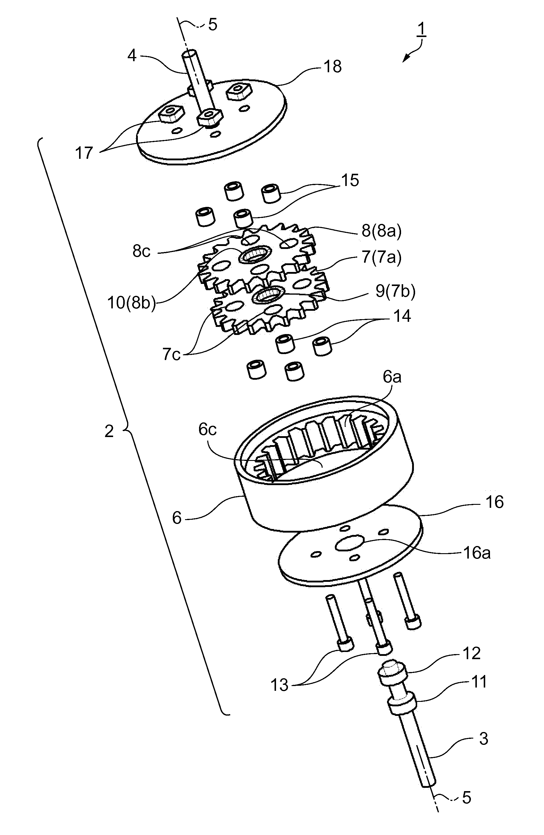
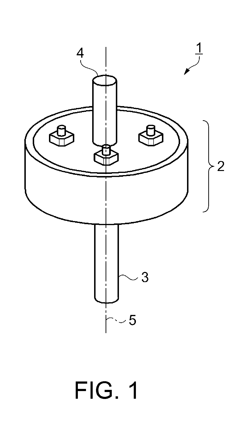
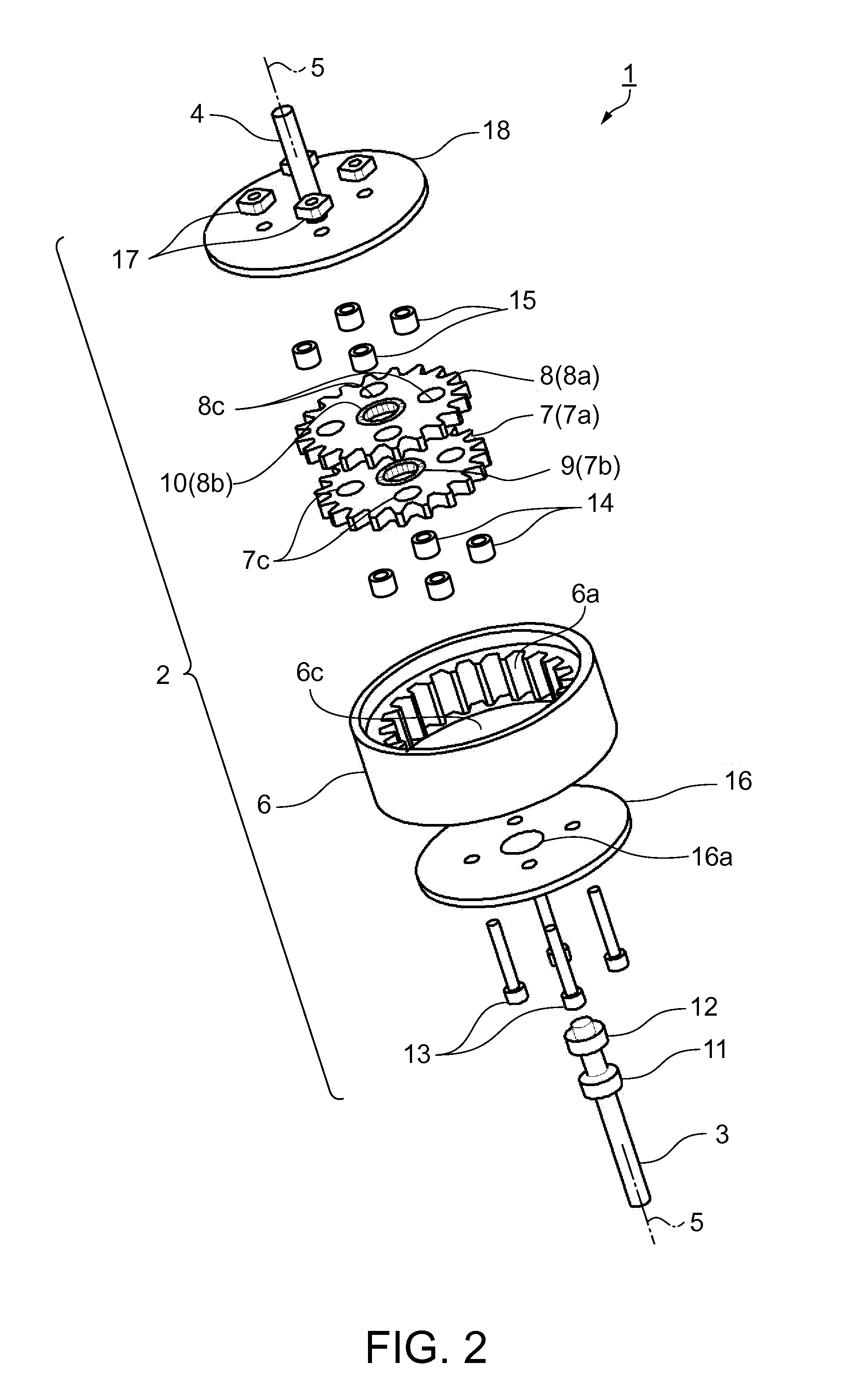
[0049]FIG. 1 is a schematic perspective view showing the appearance of a speed reducer. As shown in FIG. 1, a speed reducer 1 includes a cylindrical main body section 2. At one end of the main body section 2 in the axial direction thereof, a first rotating shaft 3 is provided, and, at the other end of the main body section 2 in the axial direction thereof, a second rotating shaft 4 is provided. The first rotating shaft 3 and the second rotating shaft 4 rotate about the same central axis 5. In addition, an axis of the main body section 2 is also disposed on the same line as the central axis 5. When the first rotating shaft 3 is rotated in a state in which the main body section 2 is fixed, the speed of the rotation is reduced by a mechanism in the main body section 2 and is output from the second rotating shaft 4. That is, the first rotating shaft 3 is an input shaft that rotates at high speed, and the second rotating shaft 4 is an output shaft that rotates at a lower speed.

[0050]FIG....

second embodiment

[0096]Next, another embodiment of the speed reducer will be described by using FIG. 5A. This embodiment differs from the first embodiment in that the first elastic section 14 is fixed to the first revolving gear 7. It is to be noted that descriptions of the same component elements as those of the first embodiment will be omitted.

[0097]That is, in this embodiment, as shown in FIG. 5A, the first elastic section 14 is inserted into the first through hole 7c. In addition, the first elastic section 14 is fixed to the first revolving gear 7. As a method for fixing the first elastic section 14 to the first revolving gear 7, a method using an adhesive, a method by which the first elastic section 14 is press-fitted into the first through hole 7c, a method by which the first elastic section 14 is inserted into the first through hole 7c by changing a temperature, such as shrinkage fit and expansion fit, and other methods can be used. In this embodiment, for example, the method by which the fir...

third embodiment

[0102]Next, still another embodiment of the speed reducer will be described by using schematic sectional views of the elastic sections of FIGS. 7A to 7G. This embodiment differs from the first embodiment in the cross-sectional shapes of the first elastic section 14 and the second elastic section 15. It is to be noted that descriptions of the same component elements as those of the first embodiment will be omitted.

[0103]That is, in this embodiment, as shown in FIG. 7A, a fourth elastic section 25 may be disposed between the through pin 13 and the first revolving gear 7. Moreover, the fourth elastic section 25 may be disposed between the through pin 13 and the second revolving gear 8. A face where the fourth elastic section 25 makes contact with the through pin 13 is referred to as a fourth inner periphery 25a, and a face where the fourth elastic section 25 makes contact with the first revolving gear 7 is referred to as a fourth outer periphery 25b. The fourth elastic section 25 is di...


PUM


Abstract

A speed reducer includes a ring gear having internal gear teeth, a revolving gear meshing with the ring gear, an eccentric cam relatively rotatably provided in a center of the revolving gear, a first rotating shaft in the eccentric cam, the first rotating shaft driving the revolving gear by rotating the eccentric cam, a through pin inserted into a through hole in the revolving gear, a second rotating shaft connected to the through pin and outputting rotation obtained by the rotation of the revolving gear, and an elastic section between the through hole and the through pin, the elastic section having a greater area of contact with the through pin than with the through hole.

Description

BACKGROUND[0001]1. Technical Field[0002]The present invention relates to speed reducers, robots, and robot hands.[0003]2. Related Art[0004]The power obtained from a power source such as a motor cannot be used as it is because the rotation speed thereof is often too high or the torque thereof is often insufficient. It is for this reason that reducing the rotation speed to an adequate rotation speed by using a speed reducer to produce a desired number of revolutions and torque is widely carried out.[0005]A speed reducer by which a large reduction ratio can be obtained has been disclosed in JP-A-2008-240852. The speed reducer includes a ring gear, and a revolving gear that is slightly smaller than the ring gear and has a smaller number of teeth than that of the ring gear is provided inside the ring gear. In the center position of the revolving gear, a circular cam is provided in a state in which the circular cam can rotate with respect to the revolving gear. On the circular cam, a firs...

Claims


Application Information

Patent Timeline
Patent Type & Authority Applications(United States)
IPC IPC(8): B25J18/00F16H1/32
CPCB25J9/103Y10T74/20317F16H2001/325F16H1/32
Inventor YAMAMOTO, SOTA
Owner SEIKO EPSON CORP
Why Eureka
Try Eureka