Capacitive sense toggle touch dimmer

a touch dimmer and capacitance technology, applied in the field of capacitance sense toggle touch dimmer, can solve the problems of inability to sense or measure the capacitance change of the touch pad, inability to operate properly, and inability to work properly, so as to reduce the cost and complexity of operation

Inactive Publication Date: 2010-11-16
LEVITON MFG
View PDF41 Cites 85 Cited by
  • Summary
  • Abstract
  • Description
  • Claims
  • Application Information

AI Technical Summary

Benefits of technology

[0008]In one embodiment, the dimmer circuit includes a controller circuit that measures changes in the capacitance of the touch pad and uses these measurements to control the delivery of power from an alternating current (AC) power source to a load such as a light bulb. The touch pad, which has a capacitance, is connected to the controller through protective circuitry to prevent damage to the controller from undesirable environmental conditions such as static electricity. A measurement capacitor is connected directly to the controller and has a relatively much greater capacitance than the capacitance of the touch pad. The controller operates as a capacitance sensor in that it senses changes in the capacitance of the touch pad caused by a user touching the pad. The controller is configured by an algorithm to measure changes in the capacitance of the touch pad, recalibrate the measurements to offset negative environmental effects and determine whether the changes in capacitance correspond to various events such as a user touching or releasing the touch pad.
[0011]The controller uses the above information to turn On / Off as well as adjust the brightness of the light. The above measurement (or sensing function) is performed using the I / O pins of a controller without the need for other components such as an analog comparator, thereby reducing the cost and complexity of operation. In addition, because the algorithm is concerned with change in capacitance, the dimmer circuit is capable of operating properly even if the polarity of the electrical connection (phase and neutral lines) between the dimmer circuit and the power source is reversed.

Problems solved by technology

However, such techniques may not work properly if the electrical connection between the dimmer circuit and the AC power is reversed.
That is, if the polarity of the connection is reversed, (phase line connected to neutral terminal and neutral line connected to phase terminal) then the dimmer circuit may not be able to sense or measure the small leakage current and capacitance changes in the touch pad and thus not operate properly.

Method used


Image

  • Capacitive sense toggle touch dimmer
  • Capacitive sense toggle touch dimmer
  • Capacitive sense toggle touch dimmer

Examples


Embodiment Construction

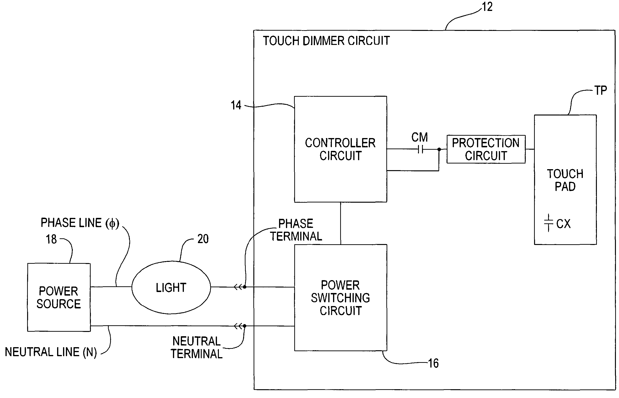
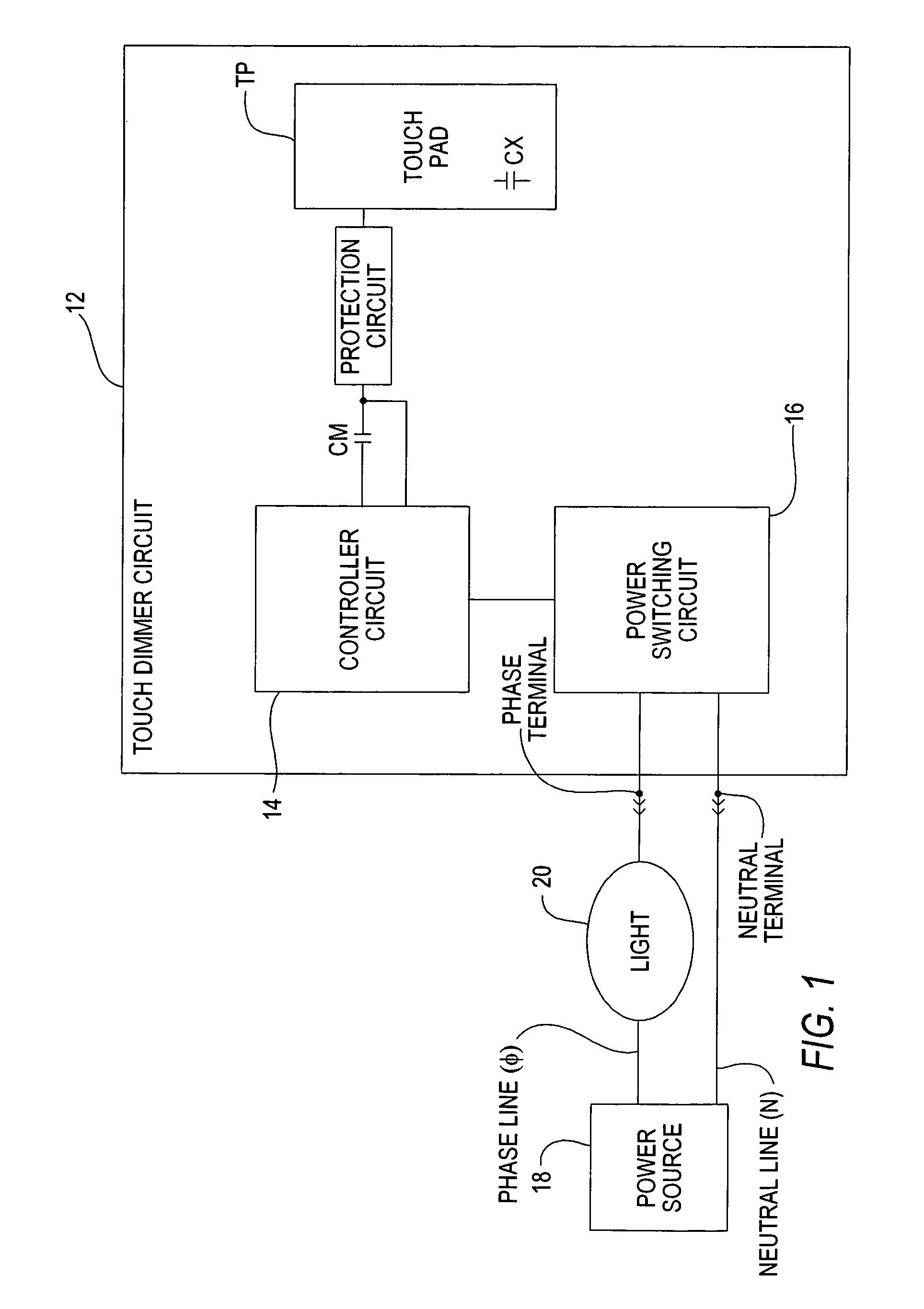
[0021]The present invention is directed to a touch / toggle dimmer circuit that includes a controller coupled to a measurement capacitor whose capacitance is known, and also coupled to a touch pad where the controller is configured by an algorithm to measure changes in the capacitance of the touch pad in response to a user touching the pad. These measurements are used to adjust the power delivered to a load independent of the polarity of the connection between the power source and the dimmer circuit.

[0022]FIG. 1 is a block diagram of a capacitance sense touch dimmer circuit 12 having a controller circuit 14 and a power switching circuit 16. The dimmer circuit 12 includes phase and neutral terminals which are connected to respective phase and neutral lines of alternating current (AC) power source 18. The controller circuit 14 measures changes in the capacitance of touch pad TP and uses these measurements to control the delivery of power from the AC power source 18 to a load such as a l...


PUM


Abstract

A touch / toggle dimmer circuit that includes a controller coupled to at least one measurement capacitor whose capacitance is known, and at least one touch pad where the controller is configured by an algorithm to measure changes in the capacitance of the touch pad in response to a user touching the pad. These measurements are used to adjust the power delivered to a load independent of the polarity of the connection between the power source and the dimmer circuit.

Description

[0001]This application claims priority of U.S. provisional application having Ser. No. 60 / 566,827, filed Apr. 30, 2004.BACKGROUND OF THE INVENTION[0002]1. Field of the Invention[0003]This invention relates generally to electrical lighting control devices and more particularly to a capacitive sense toggle touch dimmer.[0004]2. Description of the Prior Art[0005]A typical dimmer circuit adjusts the power delivered to at least one light bulb in response to a user touching a touch pad actuator. The touch pad actuator is “usually” made from metallic material. A small leakage current flows from the dimmer circuit to the user when the user touches the actuator. This flow causes the capacitance of the touch pad to change and a small voltage drop to develop across the user. A dimmer circuit can measure this change in touch pad capacitance and respond by adjusting, for example, the brightness level as well as the On / Off state of the light bulb. The dimmer circuit includes phase and neutral ter...

Claims


Application Information

Patent Timeline
Patent Type & Authority Patents(United States)
IPC IPC(8): G09G5/00H05B37/02
CPCH05B39/085H05B39/086
Inventor GRINSHPOON, MICHAELOSTROVSKY, MICHAEL
Owner LEVITON MFG
Why Eureka
Try Eureka