Electric fence energiser output energy control

a technology of energiser and output energy, applied in the field of electric fences, can solve the problems of proving lethal to such a person, the minimum delay of one pulse, etc., and achieve the effect of further control of the energy level applied

Inactive Publication Date: 2010-11-16
HURLY LESLIE SEAN
View PDF6 Cites 2 Cited by
  • Summary
  • Abstract
  • Description
  • Claims
  • Application Information

AI Technical Summary

Benefits of technology

[0022]A plurality of pulse generators may be used and interconnected so that pulses from the respective pulse trains output by the pulse generators can be interwoven in time thereby to provide a further degree of control over the energy level applied to the fence.

Problems solved by technology

A problem with this type of situation is that there is always a minimum delay of one pulse in the adaption of the energiser output energy level applied to the fence.
Thus, if a person touches a heavily loaded fence and the load condition then changes to a lighter load, a substantial amount of energy can be injected into the fence before the energy level is dropped, and this may prove to be lethal to such a person.

Method used


Image

  • Electric fence energiser output energy control
  • Electric fence energiser output energy control
  • Electric fence energiser output energy control

Examples


Embodiment Construction

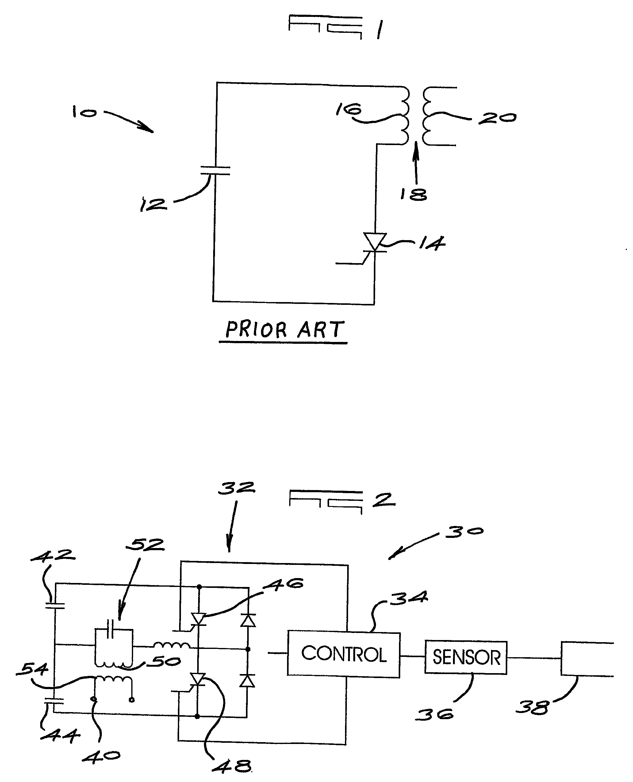
[0029]The use of energisers which produce mono-polar pulses for fence excitation is fairly standard. Such energisers are however not highly efficient in energy usage with an energy conversion factor in excess of 70% being difficult to obtain. This factor is given by the ratio of energiser output energy to stored energy.

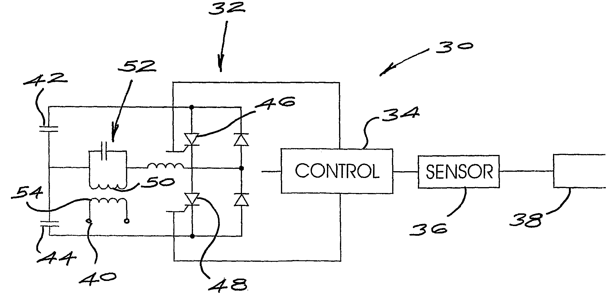
[0030]The present invention is based on the use of bi-polar and mono-polar pulse trains which can achieve energy conversion factors of the order of 90%.

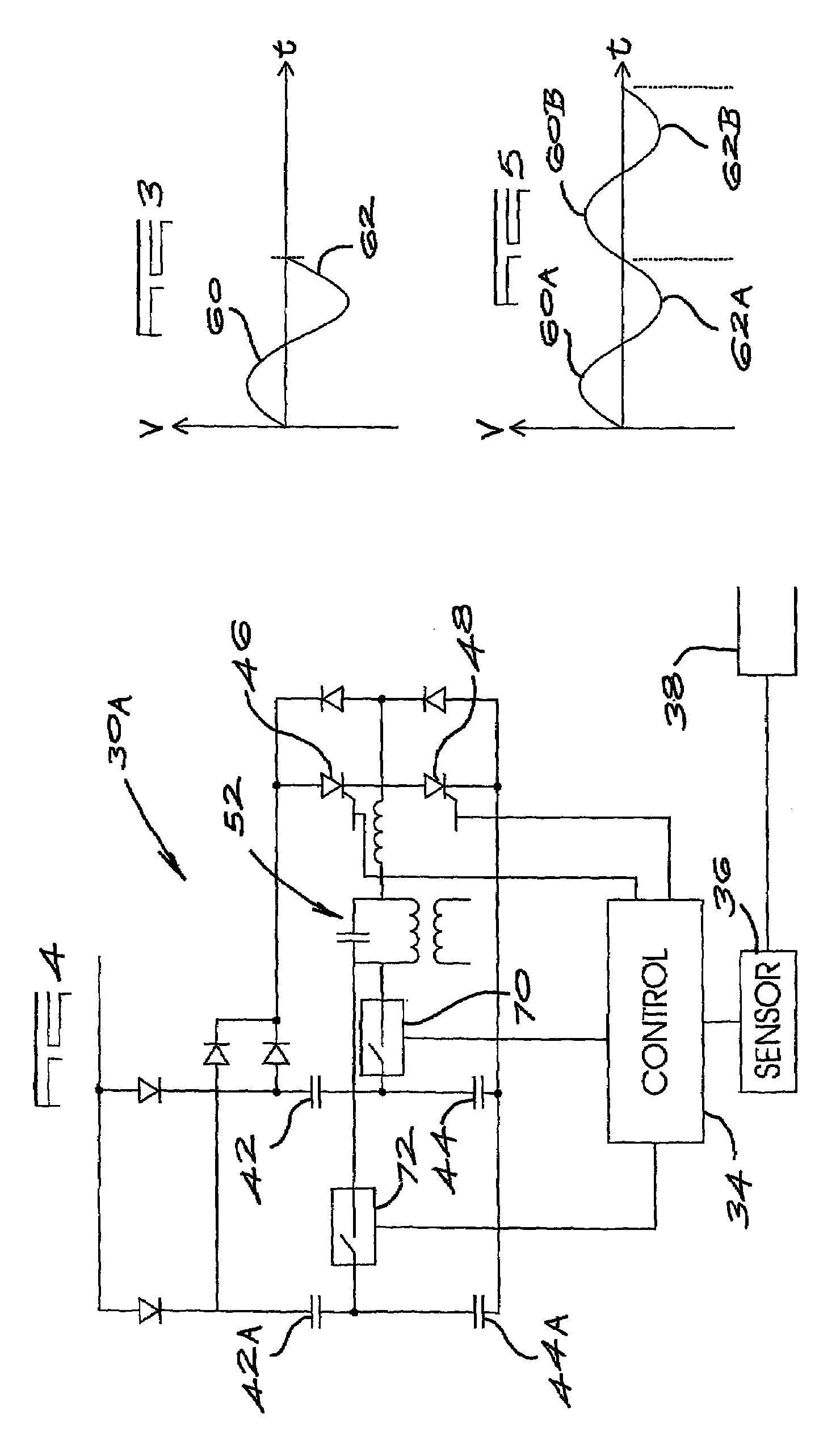
[0031]In broad terms in accordance with the principles of the invention, a fence is energised with pulses selected from a bi-polar pulse train. The fence loading is monitored during the first half of a bi-polar waveform and, if the loading is acceptable, the second half of the waveform, which is a pulse of opposite polarity to the first half, is generated and applied to the fence. However if the load conditions change adversely during the first half of the bi-polar waveform the second half of the waveform is not genera...


PUM


Abstract

An electric fence energizer which includes a pulse generator which produces a bi-polar pulse train and a control circuit which applies a mono-polar pulse, or a bi-polar pulse, derived from the pulse train to the fence in response to a load condition on the fence.

Description

BACKGROUND OF THE INVENTION[0001]This invention relates generally to an electric fence and more particularly to controlling the output energy of one or more energisers which are used to electrify the fence.[0002]Electric fences are in widespread use inter alia for livestock control and for security purposes. It is desirable to have a high level of energy output by an energiser to make a fence excitation voltage less susceptible to electrical load conditions on a fence and, in respect of a long fence, to reduce the number of energisers. However the energy output level prevailing on the fence must be non-lethal and must comply with legislative provisions.[0003]FIG. 1 of the accompanying drawings illustrates a typical prior art arrangement 10 wherein a capacitor 12 of capacitance C is charged by an external charging circuit to a voltage V. A switch 14, in the nature of a thyristor, is used, in a controlled manner, to discharge the capacitor through a primary wounding 16 of a transforme...

Claims


Application Information

Patent Timeline
Patent Type & Authority Patents(United States)
IPC IPC(8): H03K3/00
CPCH05C1/04H05C3/00
Inventor HURLY, LESLIE SEAN
Owner HURLY LESLIE SEAN
Why Eureka
Try Eureka