Eureka AIR delivers breakthrough ideas for toughest innovation challenges, trusted by R&D personnel around the world.

Method of testing remote power line carrier pick-up coil with a single test frequency

Active Publication Date: 2010-11-16
DGI CREATIONS
View PDF39 Cites 0 Cited by
  • Summary
  • Abstract
  • Description
  • Claims
  • Application Information

AI Technical Summary

Benefits of technology

[0013]The present invention pertains to the use of power line carrier communications which introduces a high frequency analog signal onto a cable used to convey power in a portion of an electric distribution network. The analog signal is received at a distant receiver through the use of pick-up coil rather than risk damage by directly connect the receiver to the high voltage/high current power line cable. The present invention provides various ways to test the operation of the pick-up coil without having to de-energize the power line serving as the power line carrier in order to perform testing on the pick-up coil. In one implementation, a series of test frequencies are introduced and parameters of the pick-up coil can be m

Problems solved by technology

Unfortunately, the input to a receiver from a bad pick-up coil does not provide a clear indication that a pick-up coil has failed.
In some instances almost half of the 32 pick-up coils providing input to a receiver at a substation have been found to be bad upon testing.
This situation was not detected much earlier as it takes the failure of a number of pick-up coils in the same general vicinity before there is not a signal to be obtained through cross-talk.
Thus, the prior art lacks a way to efficiently test pick-up coils to verify that they are operating properly rather than feeding the receiver a crosstalk signal from a nearby pick-up coil.
The prior art also lacks a way to efficiently test pick-up coils to detect a degradation in performance so that a pick-up coil can be put on the schedule to be replaced at a convenient time before the pick-up coil degrades to the point of failure.

Method used


Image

  • Method of testing remote power line carrier pick-up coil with a single test frequency
  • Method of testing remote power line carrier pick-up coil with a single test frequency
  • Method of testing remote power line carrier pick-up coil with a single test frequency

Examples


Embodiment Construction

[0024]The present invention will now be described more fully hereinafter with reference to the accompanying drawings, in which implementations of the invention are shown in order to teach the invention to those of skill in the art.

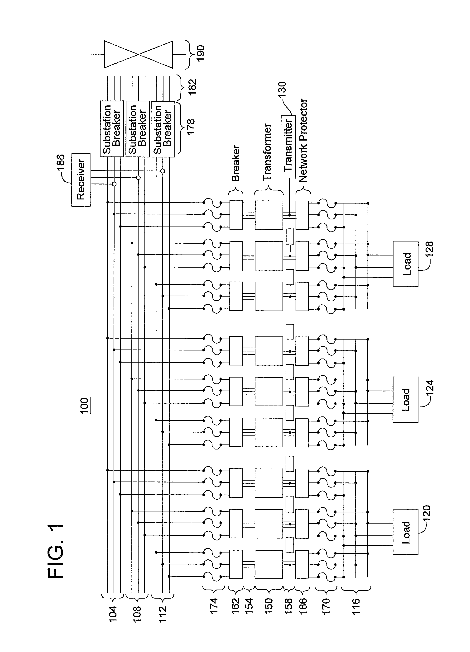
[0025]A simplified drawing is provided in FIG. 1 to introduce certain relevant components. As the focus of this application is on the testing the pick-up coil, many relevant components that would be present in an actual power grid distribution system have been omitted.

[0026]A portion of an electrical distribution network is shown as network 100. Network 100 has feeder bus 104, feeder bus 108, and feeder bus 112. A representative voltage for operation of these feeder buses may be 13 kv but other systems may operate at 27 kv, 34 kv or some other voltage. The power on these three buses is provided to a set of local distribution networks 116 to serve loads represented by 120, 124, and 128. The voltage on these local distribution networks is apt to be 120 volts...


PUM


Abstract

Methods to test the operation of the pick-up coil without having to de-energize the power line serving as the power line carrier in order to perform testing on the pick-up coil. A series of at least one test frequency is introduced and parameters of the pick-up coil can be measured to detect the presence or absence of resonant behavior indicative of the health of the pick-up coil. Testing capabilities may be incorporated into a power line carrier receiver and use the connections between the pick-up coils and the receiver to perform the pick-up coil test. Several methods for evaluating the pick-up coil response to a series of test inputs of different frequencies are presented. These methods could be incorporated in a pick-up coil testing device that is independent of a receiver.

Description

[0001]This application is a divisional of and claims priority and incorporates by reference U.S. patent application Ser. No. 11 / 500,713 filed Aug. 8, 2006 for Method of Testing Remote Power Line Carrier Pick-Up Coil. The '713 application is a continuation-in-part of U.S. patent application Ser. No. 11 / 453,272 (now U.S. Pat. No. 7,606,298) which in turn claims reference to United a States Provisional Application for Method of Testing Remote Power Line Carrier Pick-Up Coil having Ser. No. 60 / 690,244. The '713 is application claims priority and incorporates by reference U.S. Provisional Application No. 60 / 764,656 For Method of Testing Remote Power Line Carrier Pick-Up Coil. The '713 application claims priority and incorporates by reference both a related application, U.S. application Ser. No. 11 / 113,843 (Now U.S. Pat. No. 7,242,729) for Signal Decoding Method and Apparatus and its priority document U.S. Provisional Application No. 60 / 565,501 which describe a particular way to process t...

Claims


Application Information

Patent Timeline
IPC IPC(8): H04L27/06
CPCH04B3/546H04L1/24H04B2203/542H04B2203/5458H04B2203/5466
Inventor WEBER, JR., JOHN ROBERTHEISTERMANN, FRITZ
Owner DGI CREATIONS
Why Eureka
Eureka Blog
Learn More