
Method and apparatus for assay in utilizing attenuated total reflection

a total reflection and assay technology, applied in the field of method and apparatus for assays in utilizing attenuated total reflection, can solve the problems of excessively short measuring time, excessive long measuring time for a first sample of the first sample of the reaction speed, and low reaction speed of the sampl

Inactive Publication Date: 2010-11-23
FUJIFILM CORP +1
View PDF12 Cites 4 Cited by
  • Summary
  • Abstract
  • Description
  • Claims
  • Application Information

AI Technical Summary

Benefits of technology

The present invention provides a method and apparatus for assay in utilizing attenuated total reflection. The method includes steps of introducing a sensing surface, immobilizing a ligand thereon, and measuring the reaction of binding between an analyte and the ligand. After the reaction, the sensing surface is washed using a washing fluid. The cleanliness of the sensing surface is evaluated based on a comparison of the initial and washed assay signals. The apparatus includes a sensor unit with a thin film and a transparent dielectric medium, a light source device, a photo detector, a fluid dispenser, and a data analyzer. The apparatus can effectively clean the sensing surface and ensure the accuracy of the assay results.

Problems solved by technology

A second one of the samples with a low value of the reaction speed will take considerable time for obtaining a result of reaction.
If a measuring time between the start and end of the assay is kept unchanged between samples, the measuring time is excessively long for a first one of the samples of which the reaction speed is high.
The measuring time is excessively short for a second one of the samples of which the reaction speed is low.
Should the washing time be too short, the washing is incomplete.
Should the washing time be too long, the throughput or efficiency cannot be high.

Method used


Image

  • Method and apparatus for assay in utilizing attenuated total reflection
  • Method and apparatus for assay in utilizing attenuated total reflection
  • Method and apparatus for assay in utilizing attenuated total reflection

Examples


Embodiment Construction

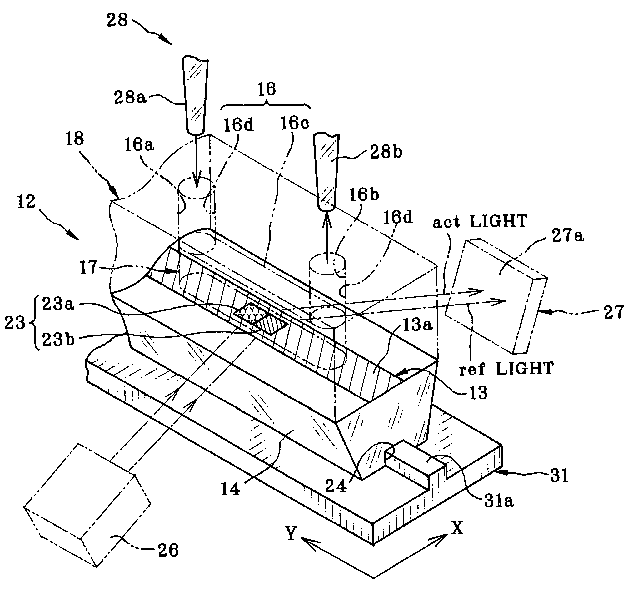
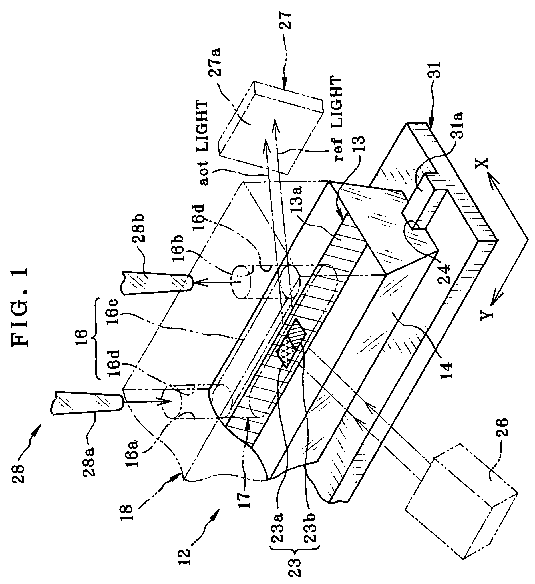
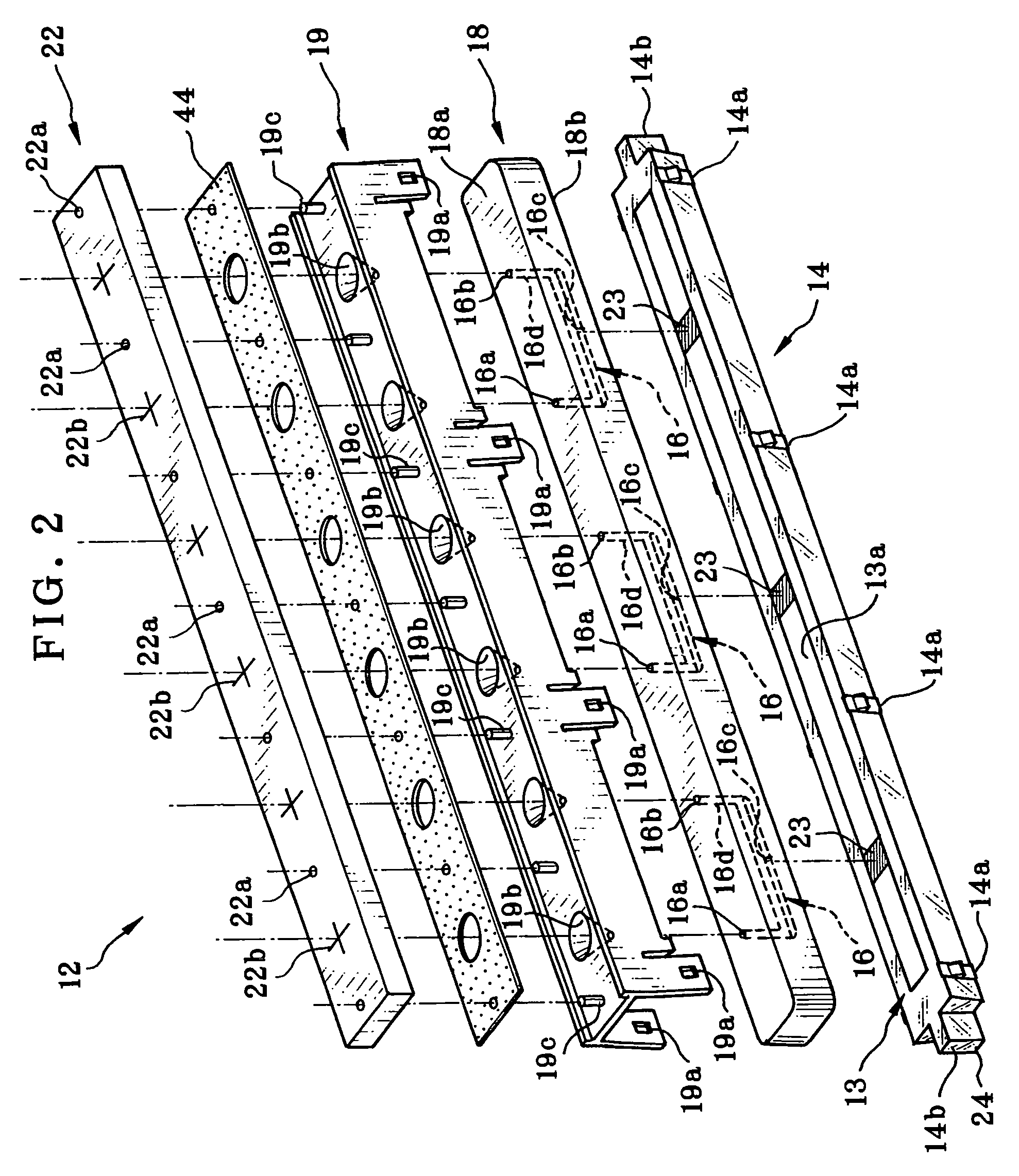
[0052]In FIG. 1, a surface plasmon resonance (SPR) apparatus is provided with a sensor unit 12 for detecting association and / or dissociation between ligand and analyte. The assay apparatus includes an optical assay unit for detection, and a multi channel dispensing head or fluid dispenser 28 as two pipette devices 28a and 28b dispense or aspirate with a flow channel 16. The optical assay unit includes a light source device 26 and a photo detector 27. The light source device 26 emits light beams to the sensor unit 12 at plural incident angles to satisfy the total reflection condition. The photo detector 27 receives the reflected light from the sensor unit 12, and detects intensity of the reflected light. The photo detector 27 outputs an assay signal constituted by light intensity distribution on the photo reception surface. Reaction of the sample is measured by analyzing the assay signal according to changes in the resonance angle.

[0053]In FIG. 2, the sensor unit 12 includes a transp...


PUM

PropertyMeasurementUnit
diameteraaaaaaaaaa
transparentaaaaaaaaaa
timeaaaaaaaaaa

Abstract

A surface plasmon resonance (SPR) assay apparatus is provided, in which a flow channel, a sensing surface and an optical assay unit are used. The sensing surface is associated with the flow channel, and contacted by a sample in the flow channel. The optical assay unit applies illuminating light to the sensing surface in contact with the sample, and measures reaction of the sample according to the illuminating light being reflected. A fluid dispenser, after measuring the reaction of the binding, introduces washing fluid on the sensing surface to wash the sensing surface. A cleanliness evaluator, according to the assay signal in the washing, checks whether a regenerated state of the sensing surface is such that the sensing surface is regenerated to an initial state prior to the reaction of the binding. A controller ends up the washing if the sensing surface has been regenerated to the initial state.

Description

BACKGROUND OF THE INVENTION[0001]1. Field of the Invention[0002]The present invention relates to a method and apparatus for assay in utilizing attenuated total reflection. More particularly, the present invention relates to a method and apparatus for assay in utilizing attenuated total reflection in which a sensing surface in a flow channel can be washed sufficiently and rapidly.[0003]2. Description Related to the Prior Art[0004]An assay apparatus for assay in utilizing attenuated total reflection is used for various kinds of studies in a biochemical field or the like, for example to study interaction of protein, DNA and various biomaterials, and to select candidate drugs by screening. Also, the technique is useful in the fields of the clinical medicine, food industries and the like.[0005]A surface plasmon resonance (SPR) sensor is known as an assay apparatus in utilizing attenuated total reflection. A thin film / dielectric interface of a metal film is fitted on a dielectric block. L...

Claims


Application Information

Patent Timeline
Patent Type & Authority Patents(United States)
IPC IPC(8): G01N21/00G01N33/53G01N21/75G01N21/47G01N21/31G01N21/17G01N21/01
CPCG01N33/54373
Inventor MURAISHI, KATSUAKI
Owner FUJIFILM CORP
Learn More