
Apparatus and method of assay in utilizing attenuated total reflection

a technology of total reflection and apparatus, applied in the field of apparatus and method of assay in utilizing attenuated total reflection, can solve the problems of long time analysis, high signal initial rise in an early section, and high probability of errors in observation, estimation and calculation of technicians, etc., to achieve easy analysis of interaction between ligand and analyte, high throughput, and high precision

Inactive Publication Date: 2006-03-30
FUJIFILM CORP +1
View PDF6 Cites 2 Cited by
  • Summary
  • Abstract
  • Description
  • Claims
  • Application Information

AI Technical Summary

Benefits of technology

[0016] In view of the foregoing problems, an object of the present invention is to provide an apparatus and method of assay in utilizing attenuated total reflection, in which density of analyte fluid can be adjusted with high precision, and thus analysis of interaction between ligand and the analyte can be easy with a high throughput by raising precision in retrieval of a reaction curve.
[0037] Accordingly, density of analyte fluid can be adjusted with high precision because of the automated feedback control of the preparation of the analyte fluid. Analysis of interaction between ligand and the analyte can be easy with a high throughput by raising precision in retrieval of a reaction curve.

Problems solved by technology

For example, an initial rise of the signal in an early section can be too high.
Errors in observation, estimation and calculation of the technicians are very likely to occur according to specifically personal skills.
This leads to a long time analysis or an erroneous result of the analysis, which is very unsuitable for assay with high precision.

Method used


Image

  • Apparatus and method of assay in utilizing attenuated total reflection
  • Apparatus and method of assay in utilizing attenuated total reflection
  • Apparatus and method of assay in utilizing attenuated total reflection

Examples


Embodiment Construction

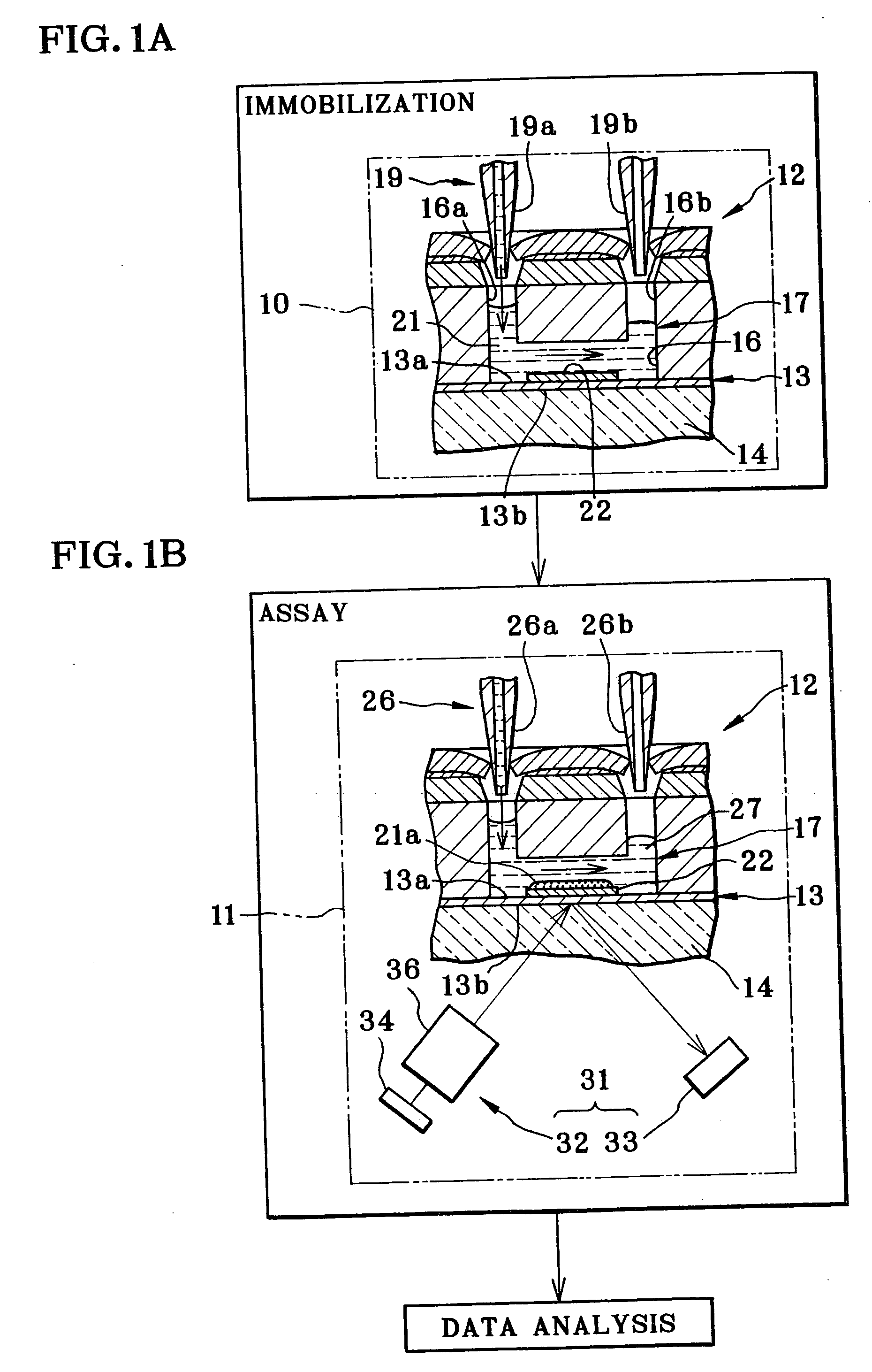
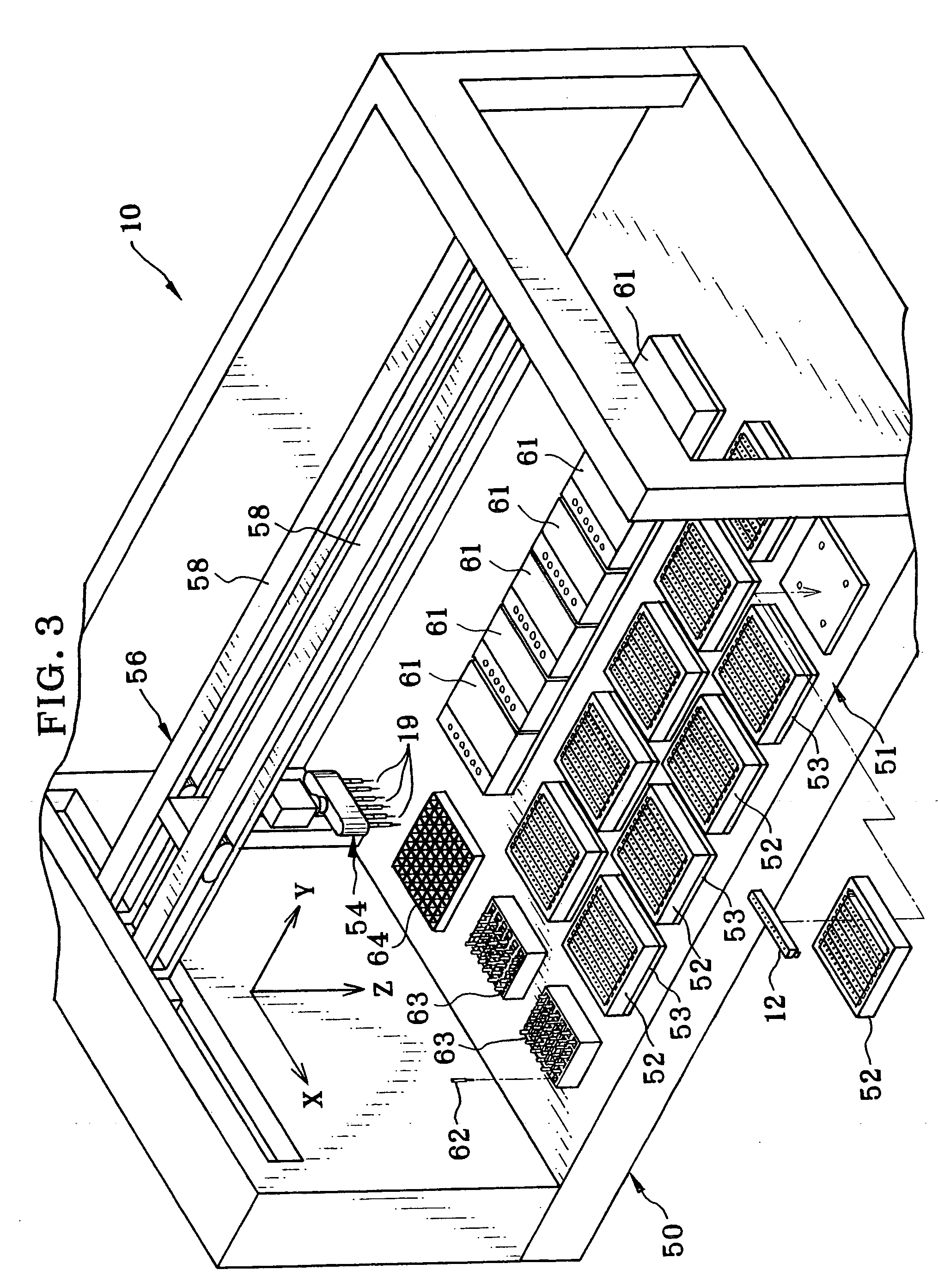
[0047] In FIGS. 1A and 1B, a system for measuring or assay according to SPR (surface plasmon resonance) is illustrated. A sequence of the assay system is constituted by three processes which are a sample immobilizing process, assay process and data analyzing process. The assay system includes a sample immobilizing device 10, an assay apparatus 11, and a data analyzer 91, which is illustrated in FIG. 4.

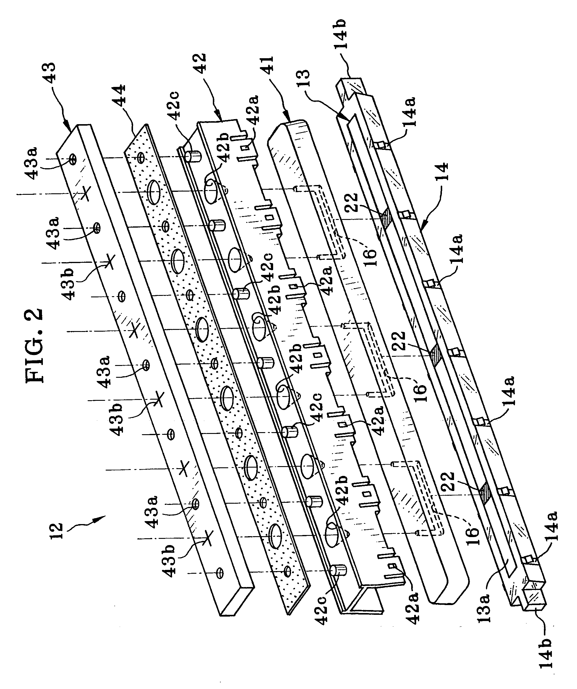
[0048] A surface plasmon resonance (SPR) biosensor is used as a sensor unit 12 for assay. The sensor unit 12 includes a metal film 13, a prism 14 and a flow channel block 41. A first surface of the metal film 13 is a sensing surface 13a where surface plasmon resonance is created. A second surface of the metal film 13 is a thin film / dielectric interface or light entrance surface 13b where the prism 14 is overlaid therewith. The flow channel block 41 has a flow channel 16, which extends along the sensing surface 13a, and causes ligand and analyte as fluids to flow.

[0049] An example of ...


PUM


Abstract

An assay apparatus is loaded with a sensor unit as surface plasmon resonance (SPR) biosensor, which includes a transparent dielectric medium and thin film. A first surface of the thin film is a thin film / dielectric interface. Its sensing surface causes reaction of sample fluid. An optical assay unit assays reaction of the sample fluid by detecting illuminating light reflected by the interface. Measured data from the optical assay unit is compared with a reference parameter, to evaluate suitability of the measured data for analysis. If lack of the suitability is estimated in the evaluation, a succeeding density of the sample fluid to be used in a succeeding evaluating assay is determined according to the measured data with the estimated lack of the suitability. The sample fluid is prepared at the succeeding density by mixing with diluent fluid, and then is used for the succeeding evaluating assay.

Description

BACKGROUND OF THE INVENTION [0001] 1. Field of the Invention [0002] The present invention relates to an apparatus and method of assay in utilizing attenuated total reflection. More particularly, the present invention relates to an apparatus and method of assay in utilizing attenuated total reflection, in which density of analyte fluid can be adjusted with high precision, and thus analysis of interaction between ligand and the analyte can be easy with a high throughput by raising precision in retrieval of a reaction curve. [0003] 2. Description Related to the Prior Art [0004] An assay apparatus in utilizing attenuated total reflection for assaying a sample is known in the field of the biosensor. U.S. Pat. No. 5,313,264 (corresponding to JP-A 4-501462) discloses a surface plasmon resonance (SPR) sensor as a typical example for this assay. [0005] A thin film, or metal film, is formed on a transparent dielectric medium. One surface of the metal film is a sensing surface where reaction o...

Claims


Application Information

Patent Timeline
IPC IPC(8): C12M1/34G01N21/27G01N21/41
CPCG01N21/272G01N2035/1032G01N21/553Y10S436/805Y10S435/808
Inventor MURAISHI, KATSUAKIOGURA, NOBUHIKO
Owner FUJIFILM CORP
Learn More