Cover for cable connectors

a cable connector and cover technology, applied in the direction of connection insulation, insulating body, coupling device connection, etc., can solve the problems of affecting the service life of components,

Active Publication Date: 2010-11-23
JOHN MEZZALINGUA ASSOC INC
View PDF25 Cites 52 Cited by
  • Summary
  • Abstract
  • Description
  • Claims
  • Application Information

AI Technical Summary

Benefits of technology

[0007]It is a principal object and advantage of the present invention to provide a cell tower component cover that may be quickly installed and / or removed in sealing relation to components mounted on cell towers.
[0008]It is a further object and advantage of the present invention to provide a cell tower component cover that maintains its sealing properties regardless of temperature fluctuations.
[0009]It is an additional object and advantage of the present invention to provide a cell tower component cover that may be used as a redundant seal in addition to pre-existing internal seals existent in connectors.
[0010]Other objects and advantages of the present invention will in part be obvious, and in part appear hereinafter.SUMMARY OF THE INVENTION
[0011]In accordance with the foregoing objects and advantages, a first aspect of the present invention provides a cover for a connector adapted to terminate a cable, wherein the connector includes a body portion and a coupler element. The cover essentially comprises an elongated body member extending along a longitudinal axis and having cable and bulkhead ends, and interior and exterior surfaces; a plurality of spaced apart grooves formed in a predetermined region of the interior surface of the body member, proximate the cable end; wherein the interior surface of the body member is adapted to sealingly envelop the connector.
[0012]A second aspect of the present invention provides a cover for a connector adapted to terminate a signal carrying cable, wherein the connector includes a body portion and a coupling element and is adapted to terminate in a bulkhead with a shank portion extending outwardly therefrom. The cover comprises an elongated body member having proximal and distal ends, interior and exterior surfaces, and extends along a longitudinal axis. The interior surface of the cover includes a first region adapted to cover at least a portion of the signal carrying cable and extending from the proximal end to a first shoulder, the first region being of a minimum, first cross-sectional diameter, a medial region adapted to cover at least the connector body portion and nut and that extends from the first shoulder to a second shoulder, the second region being of a minimum, second cross-sectional diameter that is greater than the minimum, first cross-sectional diameter, and a third region adapted to cover the shank portion and that extends from the second shoulder to the distal end, the third region being of a minimum, third cross-sectional diameter that is greater than the minimum, second cross-sectional diameter. The cover is composed of a rubber material, preferably a silicone rubber. The first region of the cover's interior surface includes a plurality of grooves formed therein, wherein each of the grooves extends in spaced parallel relation to the others, the grooves serving primarily as reservoirs for any moisture that may migrate into the cover. The exterior surface of the cover includes at least one wing formed on the exterior surface that serves as a gripping surface for a tool or manual engagement (e.g., fingers) used to remove the cover from a connector by axial sliding of the cover.

Problems solved by technology

Regardless, the cell towers and components mounted thereon are open to the environment and thus susceptible to degradation from weather related corrosive effects (e.g., moisture infiltration), pollution, debris and other elements.
Degradation of the components potentially leads to degradation of the signal quality being transmitted through the cables that carry the wirelessly received signals at the cell tower.
First, the taping requires significant time in its initial installation, and needs to be removed in order to gain access to the component when servicing the components (and then reapplied after servicing is complete). The time associated with the taping and removal thereof when servicing the components is costly. In addition, the quality of the seal is dependant on the skill of the worker that is applying the tape. As such, inconsistent application of the tape may lead to instances of ineffective sealing of components.
Second, the properties inherent in the material composition of the tape subjects the tape to size fluctuation and inconsistent adherence. If the tape contracts in colder temperatures and loses adherence strength in warmer temperatures, for example, the quality of the seal created through the tape becomes compromised in regions that experience wide temperature fluctuation. In addition, the same pollutants and other environmental factors that affect the components when unsealed may also affect the sealing quality of the tape.
While the opening and closing of the clamshell style cover facilitates quicker installation and removal in repair situations, it too is not without its drawbacks.
For instance, the plastic material becomes brittle in colder temperatures, and this reduction in ductility increases over time.
As the material becomes more brittle, the closure mechanisms lose their effectiveness often breaking or otherwise not reliably performing the closure function for which they were designed.
Furthermore, the clamshell style closures include seams that extend essentially the entire periphery of the cover, making the sealing function much more difficult when compared to covers that do not include such long seams between parts.
As such, the clamshell style covers lose their sealing effectiveness over time and in climates that routinely experience cold temperatures.

Method used


Image

  • Cover for cable connectors
  • Cover for cable connectors
  • Cover for cable connectors

Examples


Embodiment Construction

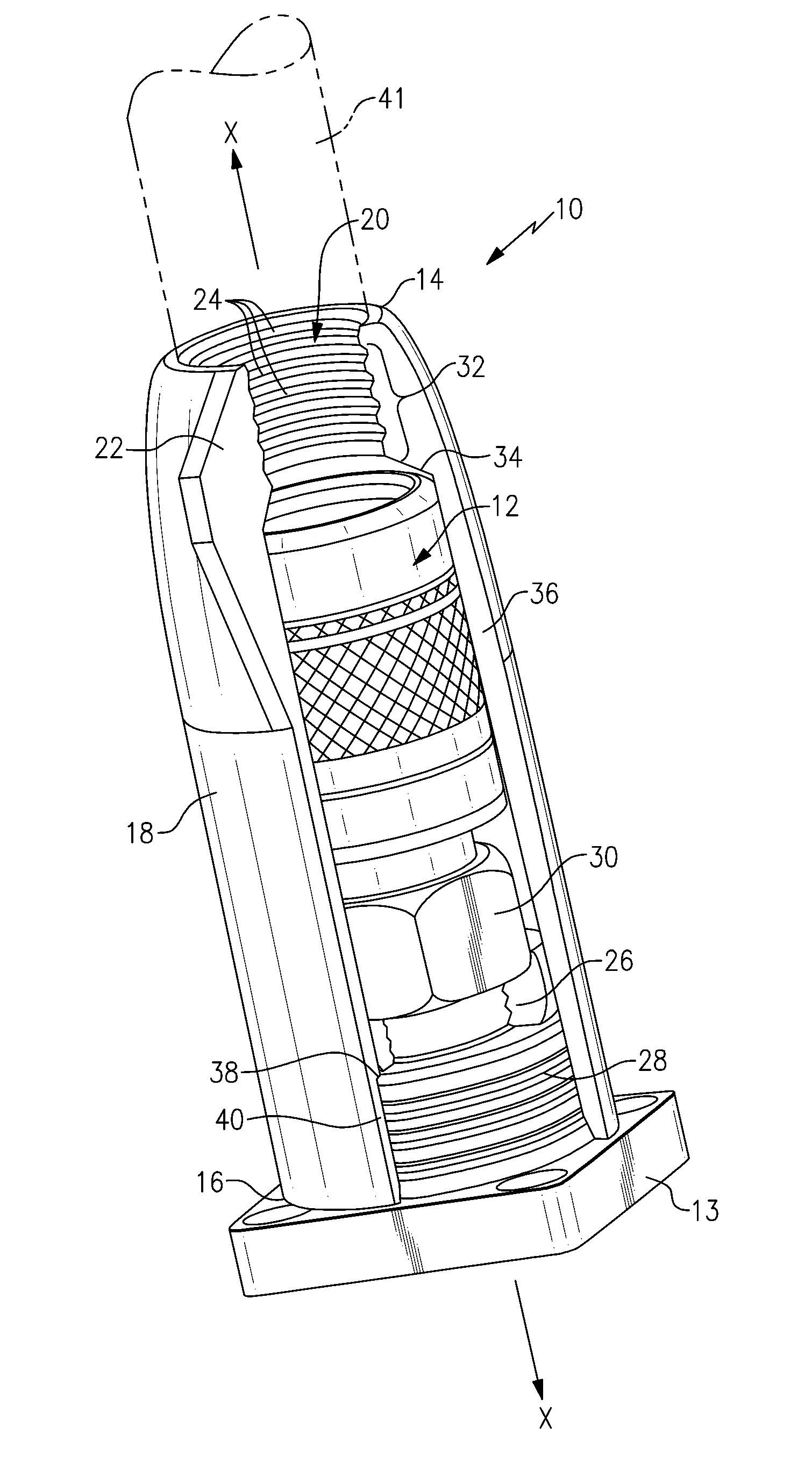
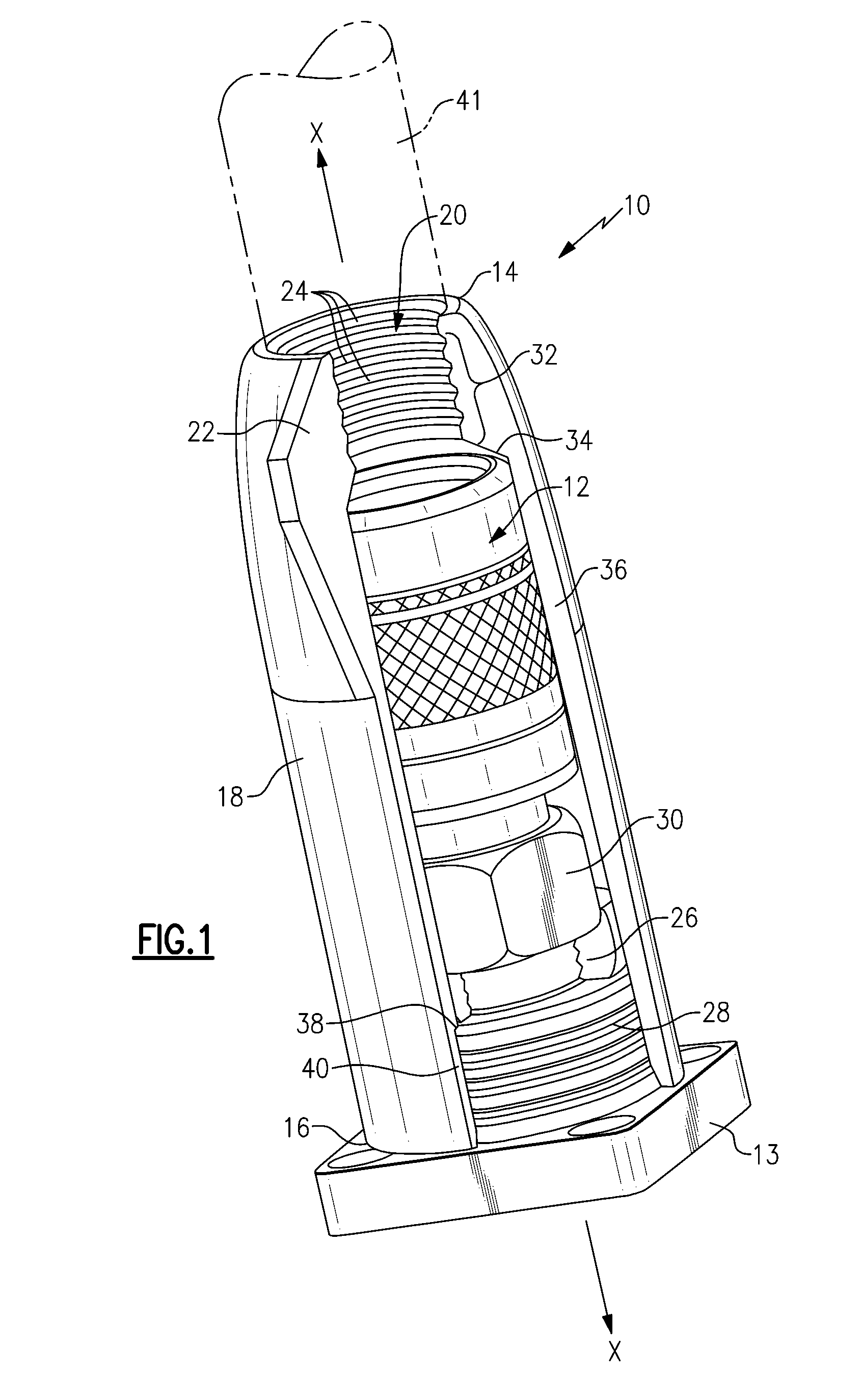
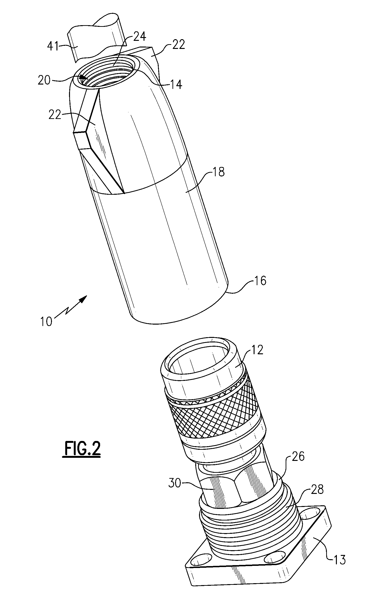
[0028]Referring now to the drawing figures in which like reference numerals refer to like parts throughout, there is seen in FIG. 1 a cover, designated generally by reference numeral 10, adapted to be placed in secure and sealing relation over a connector 12, such as (a 5-series connector manufactured by John Mezzalingua Associates, Inc. of East Syracuse, N.Y. that is adapted to terminate a ⅞″ cable). Connector 12 terminates on a bulkhead 13. In the embodiment of FIG. 1, cover 10 comprises an elongated body composed of a rubber material that exhibits a low modulus of elasticity over an extended temperature range, preferably a silicone rubber, that extends along a longitudinal axis X-X, a cable end 14, bulkhead end 16, exterior surface 18, interior surface 20, and wedge shaped wings 22 extending from opposing sides of exterior surface 18 that provide a gripping surface for a tool or manual engagement, such as pliers or a user's fingers, used to remove cover from covering relation to ...


PUM

PropertyMeasurementUnit
cross-sectional diameteraaaaaaaaaa
corrosiveaaaaaaaaaa
electricalaaaaaaaaaa

Abstract

A cover / boot and a system of covers / boots for placement in sealed relation over a connector or pair of connectors that is or are adapted to terminate a cable or splice together a pair of cables, preferably cables that carry signals received by a receiving apparatus on a cell tower. The covers include a cable end that sealingly receives a cable therein, an elongated body that provides secure cover to a cable connector, and an end that abuts a bulkhead or sealingly engages with a second cover when used in a splicing application.

Description

BACKGROUND OF THE INVENTION[0001]The present invention relates generally to covers for cable connectors, and more particularly to covers that protect cable connectors used on cell towers from environmental degradation.[0002]Cell towers contain antennas, transceivers and other wireless signal receiving apparatus mounted thereon from which a cable accepts and distributes the signal to a predetermined destination. Cell towers may be free-standing or mounted to a roof, pole, or other structure. Regardless, the cell towers and components mounted thereon are open to the environment and thus susceptible to degradation from weather related corrosive effects (e.g., moisture infiltration), pollution, debris and other elements. Degradation of the components potentially leads to degradation of the signal quality being transmitted through the cables that carry the wirelessly received signals at the cell tower.[0003]To protect the components from environmental effects, layers of tape have been us...

Claims


Application Information

Patent Timeline
Patent Type & Authority Patents(United States)
IPC IPC(8): H01B17/58
CPCH01R13/5213H01R24/40H01R2103/00
Inventor MONTENA, NOAH
Owner JOHN MEZZALINGUA ASSOC INC
Why Eureka
Try Eureka