
Ambient light sensor

a light sensor and ambient technology, applied in the field of ambient light sensors, can solve the problem that the precise measurement of the illumination of the light source cannot be carried out, and achieve the effect of wide illumination range and excellent linearity of output signals

Active Publication Date: 2010-11-23
ROHM CO LTD
View PDF2 Cites 6 Cited by
  • Summary
  • Abstract
  • Description
  • Claims
  • Application Information

AI Technical Summary

Benefits of technology

[0016]The present invention has been made to cope with the conventional problems, and it is an object of the present invention to provide an ambient light sensor which is capable of keeping excellent linearity of an output signal in a wide illumination range.

Problems solved by technology

However, because the ambient light sensor described above is so structured as to always carry out a difference between the light signals according to a constant proportion, depending on certain kinds of light sources whose illuminations are measured, the difference calculation result becomes below zero, and the output signal becomes zero, accordingly, there is a problem that exact measurement of illuminations of the light sources cannot be carried out.

Method used


Image

  • Ambient light sensor
  • Ambient light sensor
  • Ambient light sensor

Examples


Embodiment Construction

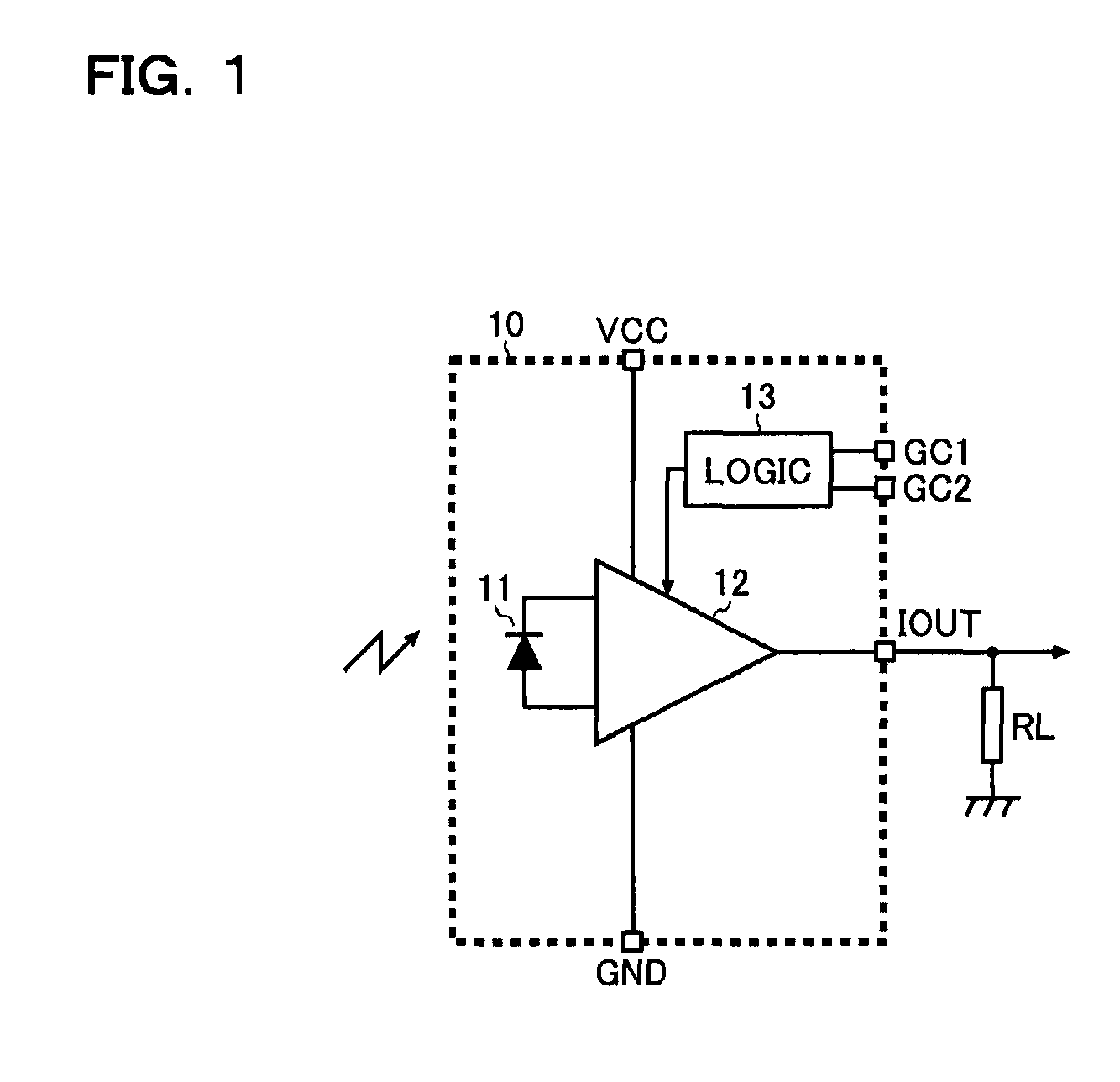
[0045]FIG. 1 is a block diagram showing an embodiment of a semiconductor apparatus according to the present invention.

[0046]An overview of a semiconductor apparatus 10 according to the present embodiment is described below.

[0047]The semiconductor apparatus 10 shown in FIG. 1 is an analog ambient light sensor IC that outputs an electric current, and, for example, is capable of outputting illumination data for implementation of brightness adjustment of a liquid crystal display screen. Besides, it is possible to decrease power consumption of a set and improve visibility of a screen by adjusting brightness of a liquid crystal display and a key pad according to illumination data.

[0048]Next, features of the semiconductor apparatus 10 are described.

[0049]A first feature is that a small surface mount package (3.0 [mm]×1.6 [mm]) is used. A second feature is that the semiconductor apparatus 10 has a spectral sensitivity characteristic near visual sensitivity (the peak sensitivity wavelength: ...


PUM


Abstract

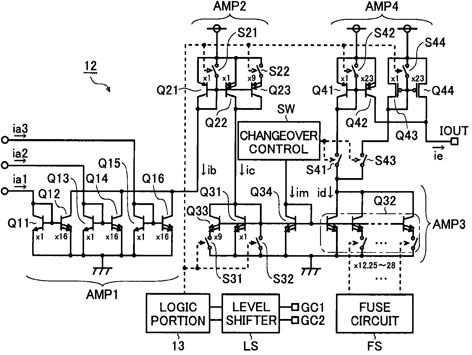
In an ambient light sensor according to the present invention, a current amplification portion which amplifies a light current obtained by a light receiving portion to generate an output signal includes: a current amplification stage that has: a first current mirror amplifier which is composed of a bipolar transistor, and a second current mirror amplifier which is composed of a field effect transistor connected in parallel with the first current mirror amplifier; and a changeover control circuit which monitors an amplified current input into the current amplification stage, and performs changeover control of the first and second current mirror amplifiers according to a value of the amplified current.

Description

CROSS-REFERENCE TO RELATED APPLICATIONS[0001]This application is based on the following Japanese Patent Applications:[0002][1] No. 2007-311906 (the filing date: Dec. 3, 2007)[0003][2] No. 2007-311909 (the filing date: Dec. 3, 2007)[0004][3] No. 2008-293624 (the filing date: Nov. 17, 2008),the contents of which are hereby incorporated by reference.BACKGROUND OF THE INVENTION[0005]1. Field of the Invention[0006]The present invention relates to an ambient light sensor which detects ambient illumination.[0007]2. Description of Related Art[0008]Conventionally, electronic apparatuses that use an ambient light sensor to detect ambient illumination and carry out various kinds of control according to the detected results are in practical use. For example, in the field of photographing apparatuses, typically, a digital still camera and a digital camcorder, exposure control and flash control are carried out according to a detected result from an ambient light sensor. Besides, in the field of l...

Claims


Application Information

Patent Timeline
Patent Type & Authority Patents(United States)
IPC IPC(8): H01J40/14
CPCG01J1/18G01J1/4204G01J1/44H03F3/08H05B41/3922
Inventor OTSUKA, SHINICHINAKATA, YUICHIROFUJINO, JUNJI
Owner ROHM CO LTD
Learn More