Detector of a radio-frequency signal

a radio frequency signal and detector technology, applied in the field of amplifiers, can solve the problems of circuit power consumption, increased power consumption of amplifiers, and increased carrier frequency power consumption, and achieve the effect of decreasing the consumption of power

Active Publication Date: 2010-11-23
STMICROELECTRONICS (ROUSSET) SAS
View PDF6 Cites 9 Cited by
  • Summary
  • Abstract
  • Description
  • Claims
  • Application Information

AI Technical Summary

Problems solved by technology

A disadvantage then is the increased power consumption of the amplifier.
This power consumption increases along with the carrier frequency, and thus with the possible transmission rate.
A disadvantage here again is the circuit power consumption.
Here again, a problem is posed with the high required power consumption.
Such an increase is not desirable for consumption reasons Such is, for example, the case for electromagnetic transponders equipped with an on board power source (battery).
In other cases, the power supply may not transmit the desired rates.

Method used


Image

  • Detector of a radio-frequency signal
  • Detector of a radio-frequency signal
  • Detector of a radio-frequency signal

Examples


Embodiment Construction

[0061]The same elements have been designated with the same reference numerals in the different drawings.

[0062]For clarity, only those elements which are useful to the understanding of the present invention have been shown and will be described. In particular, the destination of the detected or demodulated signals has not been detailed, the present invention being compatible with any current use of such signals. Further, the transmission and possible coding mechanisms have not been detailed either, the present invention being here again compatible with any amplitude modulation transmission mechanism.

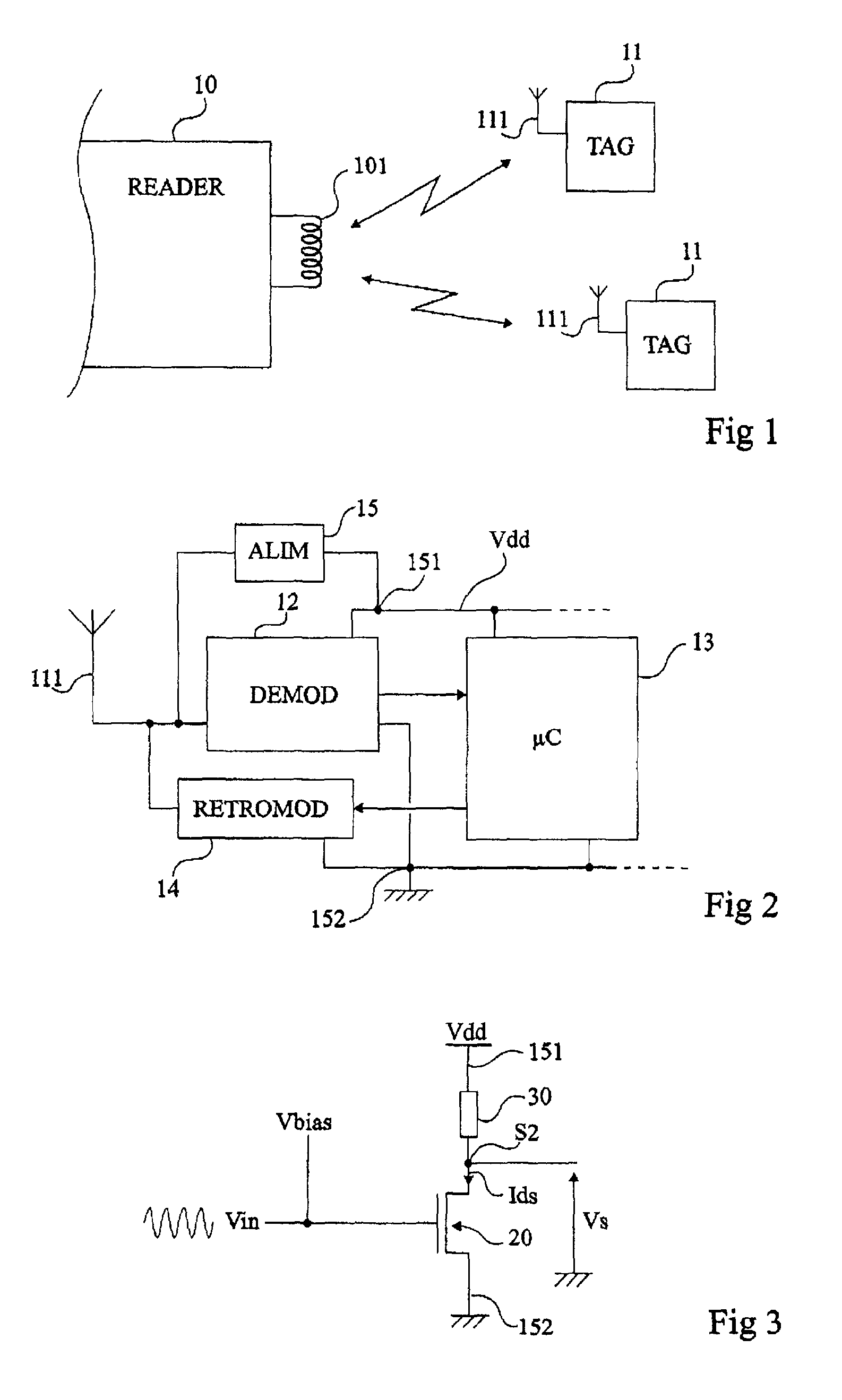
[0063]FIG. 1 very schematically shows an example of a communication system of the type to which the present invention applies as an example.

[0064]A read / write terminal 10 (READER) is capable of communicating in a contactless manner with one or several transponders 11 (TAG), for example, electronic tags. The reader comprises an oscillating circuit (for example, a series oscillating circuit...


PUM


Abstract

A method and a circuit for detecting a radio-frequency signal, including at least one first MOS transistor with a channel of a first type, having its gate coupled to an input terminal capable of receiving said signal; a circuit for biasing the first transistor, capable of biasing it to a level lower than its threshold voltage; and a circuit for determining the average value of the current in the first transistor.

Description

CROSS REFERENCE TO RELATED APPLICATIONS[0001]This application claims the priority benefit of French patent application number 07 / 58230, filed on Oct. 11, 2007, entitled “Detector of a Radio-Frequency Signal,” which is hereby incorporated by reference to the maximum extent allowable by law.BACKGROUND OF THE INVENTION[0002]1. Field of the Invention[0003]The present invention generally relates to the field of electronic circuits and, more specifically, to electronic circuits comprising a detector of radio-frequency signals, for example, for demodulation purposes.[0004]2. Discussion of the Related Art[0005]Several techniques for demodulating an amplitude-modulated radio-frequency signal are known.[0006]A first technique uses a diode with an anode which receives the signal to be demodulated and with a cathode which is connected to the input of a low-pass filter providing the envelope signal. This type of envelope detector requires that the signal to be demodulated reaches the diode with ...

Claims


Application Information

Patent Timeline
Patent Type & Authority Patents(United States)
IPC IPC(8): H03D1/00H03D1/18
CPCH03D1/00
Inventor BAS, GILLESBATTISTA, MARC
Owner STMICROELECTRONICS (ROUSSET) SAS
Why Eureka
Try Eureka