Lens barrel, camera and information device

a technology of information device and lens barrel, applied in the field of lens barrel, camera and information device, to prevent the position of the lens from changing

Inactive Publication Date: 2010-11-23
RICOH KK
View PDF14 Cites 6 Cited by
  • Summary
  • Abstract
  • Description
  • Claims
  • Application Information

AI Technical Summary

Benefits of technology

[0009]However, there is no such lens barrel in which it is possible to maintain a positional accuracy of a lens highly, to reduce a load which a cam follower receives and additionally a load which a helicoid of the rotating cylinder receives, and furthermore to prevent a lens position from changing by a load in general use.
[0010]An object of the present invention is to provide a lens barrel which makes it possible to maintain positional accuracy of a lens highly, to reduce a load which a cam follower receives and additionally a load which a helicoid of the rotating cylinder receives, and to prevent a lens position from changing by a load in general use, and to provide a camera and an information device in which the lens barrel as described above is used as an imaging optical system.

Problems solved by technology

However, there is no such lens barrel in which it is possible to maintain a positional accuracy of a lens highly, to reduce a load which a cam follower receives and additionally a load which a helicoid of the rotating cylinder receives, and furthermore to prevent a lens position from changing by a load in general use.

Method used


Image

  • Lens barrel, camera and information device
  • Lens barrel, camera and information device
  • Lens barrel, camera and information device

Examples


Embodiment Construction

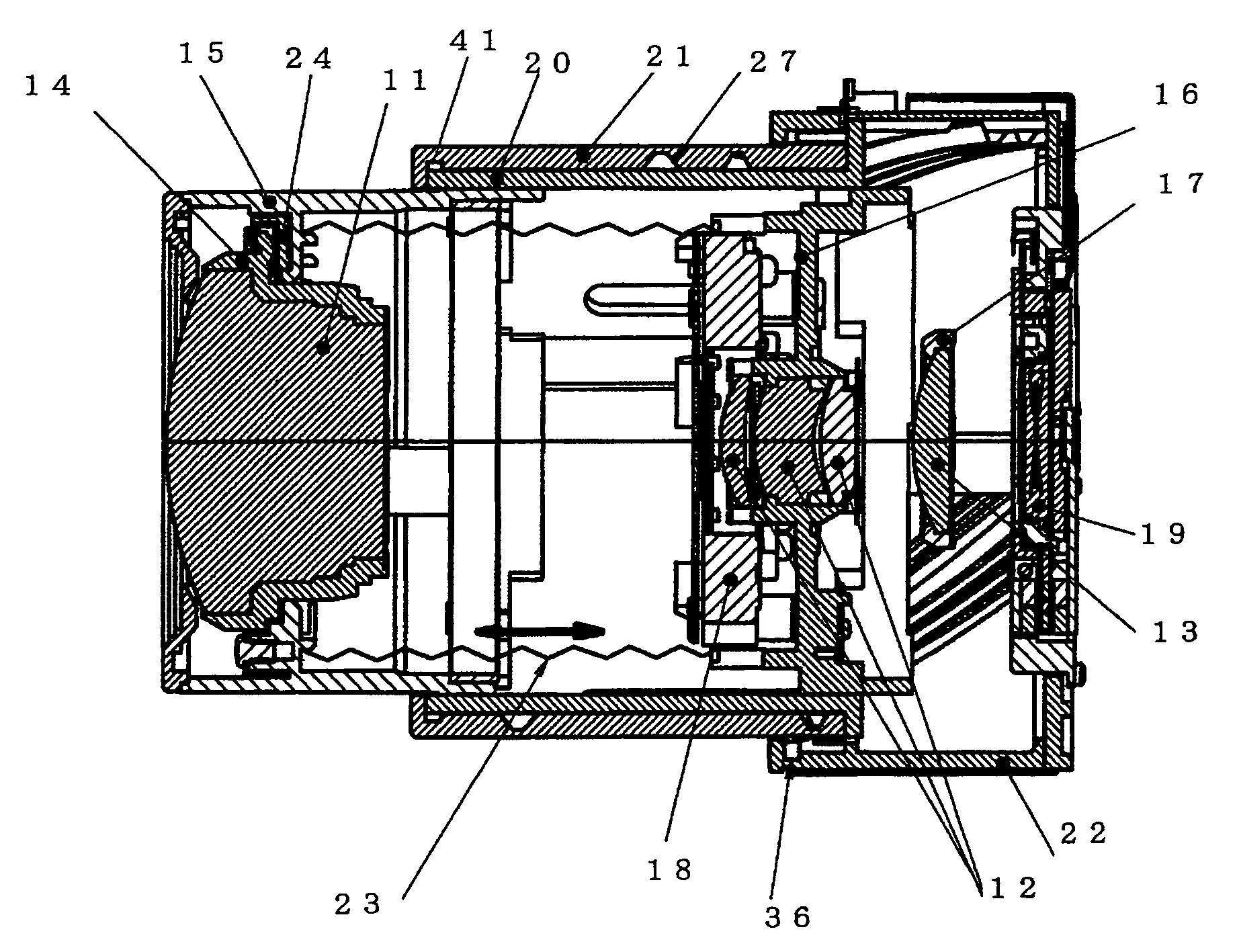
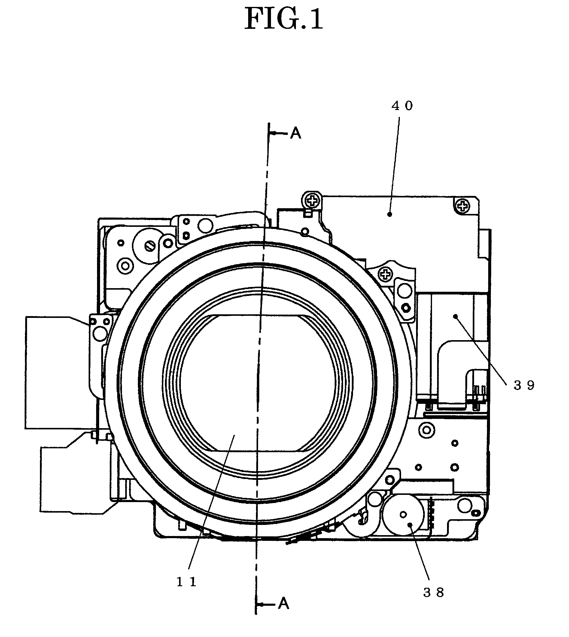
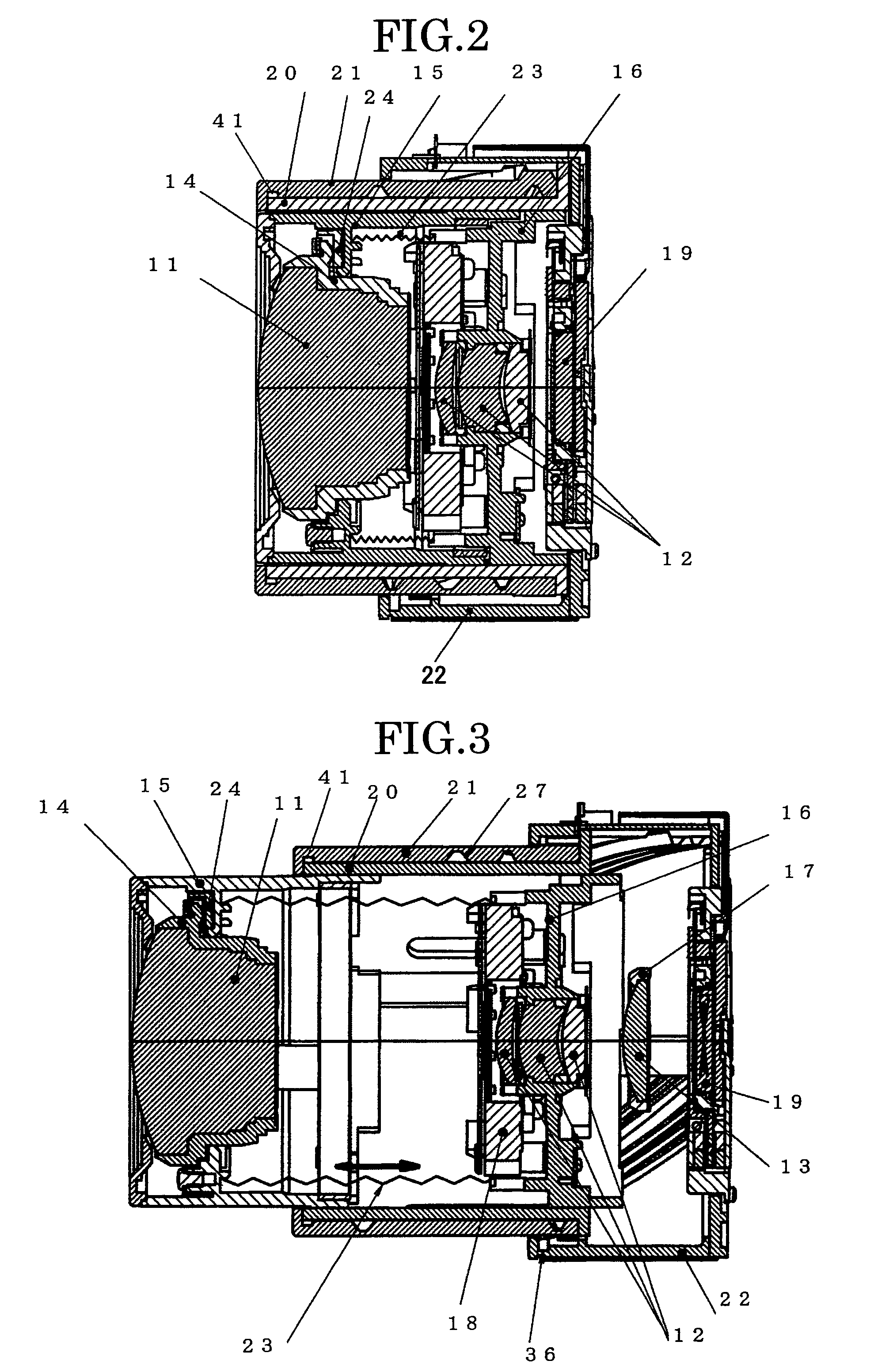
[0063]Hereinafter, based on an embodiment according to the present invention, with a reference to drawings, a lens barrel according to the present invention will be explained.

[0064]The lens barrel illustrated in FIGS. 1 to 9 includes a first group lens system 11, a second group lens system 12, a third group lens system 13, a first group lens holding frame 14, a first group lens movement frame 15, a second group lens movement frame 16, a third group lens movement frame 17, a shutter unit 18, a CCD (Charge-Coupled Device) imaging element unit 19, a linearly-guiding cylinder 20, a rotating cylinder 21, a fixed cylinder 22, a first group-second group compression spring 23, a tilt adjustment cam 24, a cam follower 25, a second group cam follower 26, a first group cam groove 27, a second group cam groove 28, a first group movement frame linear groove 29, a second group movement frame linear groove 30, a male helicoid 31, a linear key part 32, a rotating key part 33, a linear key groove 34...


PUM


Abstract

A cam locus of the cam surface (G1) on the image plane side of the first group cam groove (27) of the rotating cylinder (21) has an angle to a flat surface where the optical axis crosses perpendicularly. In a case in which the cam follower (25) engages with (abuts on) the cam surface (G1) on the image plane side, an impact force is dispersed into the optical axis direction and into the rotating direction of the rotating cylinder (21), and a load which the cam follower (25) and the male helicoid (31) of the rotating cylinder (21) receive is reduced. Additionally, when the first group lens system (11) is pressed by a light load such as a hand operation by a user and the like, the cam follower (25) of the first group lens movement frame (15) engages with (or abuts on) the cam surface (G1) on the image plane side, and an angle of the cam surface (G1) is an angle that an occurring force in the rotating direction is so as to be a moving direction from the collapsed position (S1) to the wide angle end position (W1). Therefore, the rotating cylinder (21) does not rotate easily, and when the load is removed, returns to a position before the load is received.

Description

TECHNICAL FIELD[0001]The present invention relates to a lens barrel used for an imaging optical system and to a camera and an information device in which the lens barrel is used as an imaging optical system.BACKGROUND ART[0002]Recently, regarding a lens barrel of an imaging optical system typified as a photographing lens of a camera, there have been increasing ones using a zoom lens in which positions of a plurality of lens groups are changed and the focal length is continuously changed when photographing. In this type of lens barrel, a mainstream type is a so-called collapsed-type zoom lens, which attempts to minimize its size so as to make distances between lens groups narrower and store lenses in a fixed cylinder of the lens barrel when non-photographing. As a structure of moving lenses in the lens barrel of the zoom lens and the like, there has been increasingly used such a mechanism in which a rotating cylinder is held by a fixed barrel, and when the rotating cylinder rotates r...

Claims


Application Information

Patent Timeline
Patent Type & Authority Patents(United States)
IPC IPC(8): G02B15/14G02B7/02
CPCG02B7/102G03B17/04
Inventor IWASAKI, TETSUYA
Owner RICOH KK
Why Eureka
Try Eureka