
Systems and methods for determining protective device clearing times used for providing real-time predictions about arc flash events

a technology of protection device and clearing time, applied in the field of computer simulation techniques with real-time system monitoring and electrical system performance prediction, can solve the problems of inability to apply real-time techniques, inability to reduce development costs and superior operation, and inability to use real-time techniques, etc., to achieve real-time operational monitoring and management, predictive failure analysis techniques generally do not use real-time data that reflect actual system operation

Inactive Publication Date: 2010-11-23
POWER ANALYTICS CORP
View PDF7 Cites 65 Cited by
  • Summary
  • Abstract
  • Description
  • Claims
  • Application Information

AI Technical Summary

Benefits of technology

"The patent describes a system and method for predicting the energy and duration of an arc flash event on an electrical system, and the necessary personal protective equipment to protect against it. The system uses a virtual system model of the electrical system and real-time data from sensors to make these predictions. The system can also identify the controlling paths and determine the opening times for protective devices on those paths, as well as the quantity of arc energy released by the arc flash event. The system can also determine the clearing time for the electrical system based on the fastest protective device gripping time. Overall, the system can help to improve safety standards and prevent accidents in the workplace."

Problems solved by technology

Such simulation techniques have resulted in reduced development costs and superior operation.
Design and production processes have benefited greatly from such computer simulation techniques, and such techniques are relatively well developed, but such techniques have not been applied in real-time, e.g., for real-time operational monitoring and management.
In addition, predictive failure analysis techniques do not generally use real-time data that reflect actual system operation.
It will be understood that such systems are highly complex, a complexity made even greater as a result of the required redundancy.
Once the facility is constructed, however, the design is typically only referred to when there is a failure.
In other words, once there is failure, the system design is used to trace the failure and take corrective action; however, because such design are so complex, and there are many interdependencies, it can be extremely difficult and time consuming to track the failure and all its dependencies and then take corrective action that doesn't result in other system disturbances.
Moreover, changing or upgrading the system can similarly be time consuming and expensive, requiring an expert to model the potential change, e.g., using the design and modeling program.
Unfortunately, system interdependencies can be difficult to simulate, making even minor changes risky.
For example, no reliable means exists for predicting in real-time the potential energy released for an alternating current (AC) or direct current (DC) arc flash event is available.
Moreover, no real-time system exists that can predict the required personal protective equipment (PPE) or safe distance boundaries (i.e., protection boundaries) for technicians working around components of the electrical system that are susceptible to arc flash events as required by NFPA 70E and IEEE1584.
Moreover, these conventional systems do not accurately determine the opening times (i.e., clearing times) of all the protective devices on all electrical current paths that lead to the sources of electrical energy (i.e., controlling paths).
Therefore, conventional systems cannot readily adjust to the many daily changes to the electrical system that occur at a facility (e.g., motors and pumps may be put on-line or pulled off-line, utility electrical feeds may have changed, etc.) nor accurately predict the various aspects (i.e., the quantity of energy released, the required level of worker PPE, the safe protection boundaries around components of the electrical system, etc.) related to an arc flash event occurring on the electrical system.

Method used


Image

  • Systems and methods for determining protective device clearing times used for providing real-time predictions about arc flash events
  • Systems and methods for determining protective device clearing times used for providing real-time predictions about arc flash events
  • Systems and methods for determining protective device clearing times used for providing real-time predictions about arc flash events

Examples


case 1

tective Devices Found.

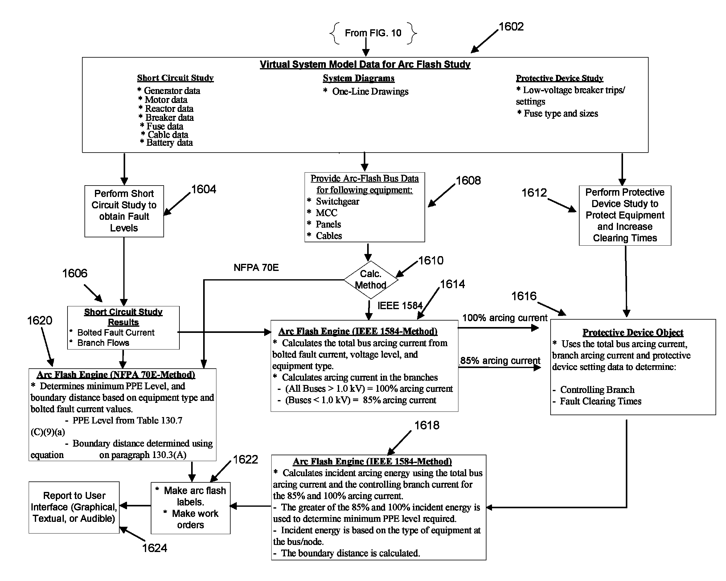
[0261]This situation occurs if the fault happens close to a source and there are no protective devices between the fault and the source. In this case the following results can be provided:

[0262]

Protective device name:No Protective device foundPPE:N / AAF Duration:N / AAF Energy:N / A

case 2

tective Devices Trip

[0263]This situation occurs when protective devices exist but the fault current is below their trip value (usually in LV network with bad coordination; 85% arcing current may become too low for the protective devices). In this case the following results can be provided:

[0264]

Protective device name:No Protective device tripPPE:Extreme dangerAF Duration:N / AAF Energy:N / A

case 3

Fault Current Exceeds Known Device Short Circuit Current

[0265]This situation occurs when Arc Flash program fails to read the tripping time of a protective device because the arcing current is bigger than the maximum value of appropriate TC characteristic. The origin of this problem is the following:[0266]User performs PDC studies for given SC level in the circuit;[0267]User decides to cut TC curves on the short circuit level; or[0268]Short circuit level in the system increases (user introduces a new source, changes switching configuration etc.).

[0269]In this case the following results can be provided:

[0270]

Protective device name:PDC exceeds device known SC *AF Duration:Set to the value from IEEE standardComment:* Short Circuit exceeds known capacity ofprotective Device; try rerunning PDC toextend to new SC level.


PUM


Abstract

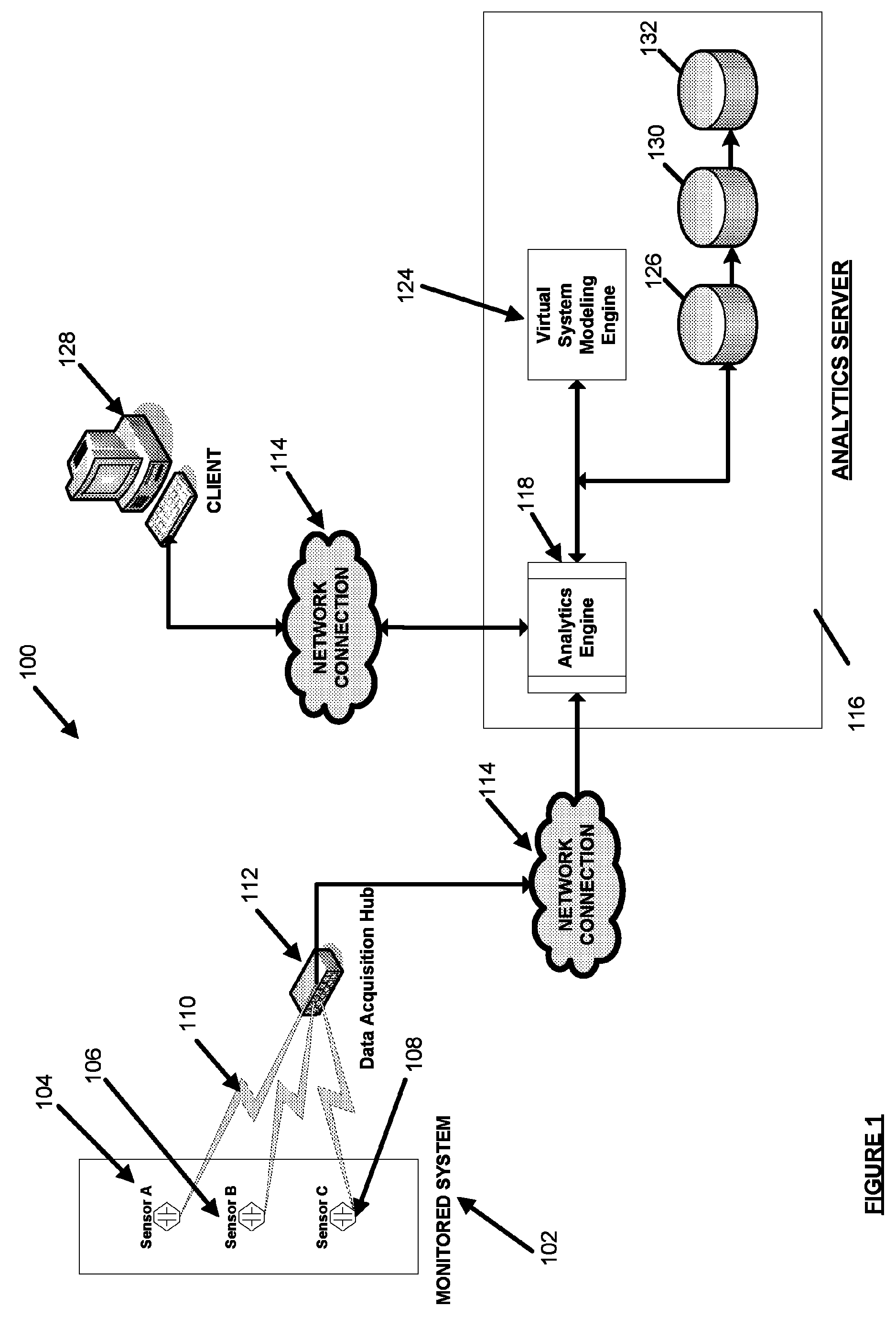
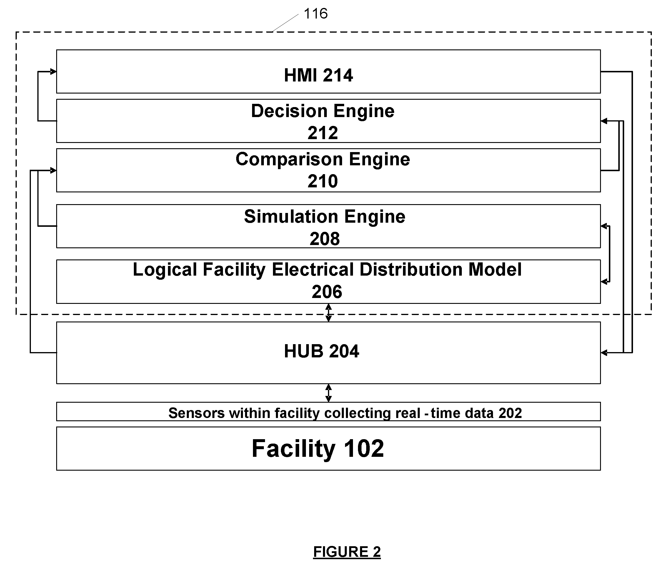
A system for making real-time predictions about an arc flash event on an electrical system is disclosed. The system includes a data acquisition component, an analytics server and a client terminal. The data acquisition component is communicatively connected to a sensor configured to acquire real-time data output from the electrical system. The analytics server is communicatively connected to the data acquisition component and is comprised of a virtual system modeling engine, an analytics engine and an arc flash simulation engine.

Description

APPLICATIONS FOR CLAIM OF PRIORITY[0001]This application claims the benefit under 35 U.S.C. §119(e) of U.S. Provisional Application Ser. No. 60 / 819,461 filed Jul. 7, 2006 and U.S. Provisional Application Ser. No. 60 / 819,035 filed Jul. 7, 2006. This application also claims priority as a Continuation-In-Part under 35 U.S.C. §120 to U.S. patent application Ser. No. 11 / 717,378, filed Mar. 12, 2007 and entitled “Systems and Methods for Real-Time Protective Device Evaluation in an Electrical Power Distribution System,” which in turn claims priority to U.S. Provisional Patent Application Ser. No. 60 / 782,329 filed Mar. 10, 2006 and U.S. Provisional Patent Application Ser. No. 60 / 806,215 filed Jun. 29, 2006. The disclosures of the above-identified applications are incorporated herein by reference as if set forth in full.BACKGROUND[0002]I. Field of the Invention[0003]The present invention relates generally to computer modeling and management of systems and, more particularly, to computer simu...

Claims


Application Information

Patent Timeline
Patent Type & Authority Patents(United States)
IPC IPC(8): G06F7/60G06F17/10G06G7/62G06G7/54
CPCG05B17/02
Inventor RADIBRATOVIC, BRANISLAVPAN, JUNNASLE, ADIB
Owner POWER ANALYTICS CORP
Learn More