Method of manufacturing photonic crystal fiber using structure-indicating rods or capillaries

a technology of structure-indicating rods and photonic crystal fibers, which is applied in the direction of manufacturing tools, optical fibers with polarisation, instruments, etc., can solve the problems of difficult to grind a columnar rod into a cylinder with great precision, and the technique is not suitable for fabricating a long pcf, so as to achieve easy recognition

Inactive Publication Date: 2010-11-30
MITSUBISHI CABLE IND LTD
View PDF25 Cites 7 Cited by
  • Summary
  • Abstract
  • Description
  • Claims
  • Application Information

AI Technical Summary

Benefits of technology

[0008]An object of the present invention is to provide a method for manufacturing a PCF which allows closest packing of capillaries for forming a cladding in an easy and reliable manner.
[0010]According to the above-described manufacturing method, a spacer is arranged between the support tube and the capillaries to provide the inner wall surface of the support tube with a substantially regular hexagonal cross-sectional shape which allows closest packing of the core rod and the capillaries or the capillaries only. The thus arranged spacer prevents the capillaries from being disarranged and the core from being misaligned with the center. As a result, a preform is obtained while almost all the capillaries are closest packed as a bundle in the support tube via the spacer. Then, by drawing the preform into a thin fiber, almost 100% of the packed capillaries function as photonic crystal after the drawing. Since the arrangement of the capillaries is controlled by the spacer, the capillaries for forming the cladding are closest packed with ease and reliability. Further, since the spacer is formed of two or more spacer parts, the inner wall surface of the spacer is shaped to have a desired substantially polygonal cross-sectional shape in an easy and reliable manner. Since the method is also applicable to a long support tube, a long PCF is obtained.
[0012]In the above-described method, the inner wall surface of the spacer is given a substantially regular hexagonal cross-sectional shape. Therefore, in filling the support tube with the cylindrical capillaries of the same diameter, the capillaries are laid side by side over one of the sides of the inner wall surface of the spacer to form a first layer of capillaries and then additional capillaries are stacked on the first layer to fit between adjacent pairs of the capillaries forming the first layer to form a second layer. By repeating these steps, the capillaries are closest packed in the support tube. Thus, it is hardly necessary to take care not to disturb the arrangement of the capillaries and therefore the packing of the capillaries in the support tube is carried out with higher efficiency. This allows the closest packing of the capillaries for forming the cladding in an easy and reliable manner.
[0014]In the above-described method, the degree of freedom of the capillaries in the drawing step is greatly reduced. Therefore, the capillaries are effectively prevented from being disarranged. Further, if the cross-sectional shape of the inner wall surface of the spacer is adjusted, capillaries of various diameters can be employed.
[0018]In the above-described method, structure-indicating rods or capillaries are inserted into the holes formed by the chipped parts of the spacer and the support tube and then the drawing step is carried out. As a result, the PCF after the drawing step is provided with structure-indicating marks which are continuous along the direction of the fiber length and has a certain positional relationship with the inner structure of the PCF. The structure-indicating marks are effective for recognizing the inner structure of a polarization maintaining PCF, i.e., it allows easy recognition of the plane of polarization (a plane including a straight line connecting the centers of a pair of polarization maintaining pores and perpendicular to the cross section of the fiber).

Problems solved by technology

Since the positions of the capillaries are not fixed within the support tube while packing the capillaries into the support tube, there is a problem of great difficulty in closest-packing the cylindrical capillaries in the cylindrical support tube.
However, to obtain the inner wall surface of the support tube 3 having the substantially regular hexagonal cross-sectional shape, there is no other way than to use a common grinding technique.
Therefore, it is difficult to grind a columnar rod into a cylinder with great precision to give the inner wall surface thereof the substantially regular hexagonal cross-sectional shape.
Therefore, this technique is not suitable for fabricating a long PCF.
Thus, the technique of forming the support tube 3 whose inner wall surface has the substantially regular hexagonal cross-sectional shape is unrealistic from the technical and economic viewpoints.
As to the polarization maintaining PCFs which place great importance on axiality, the closest packing of the capillaries in the support tube is still extremely difficult.
Therefore, it is difficult to fabricate the PCF in which all the pores in the cladding function as photonic crystal.

Method used


Image

  • Method of manufacturing photonic crystal fiber using structure-indicating rods or capillaries
  • Method of manufacturing photonic crystal fiber using structure-indicating rods or capillaries
  • Method of manufacturing photonic crystal fiber using structure-indicating rods or capillaries

Examples


embodiment 1

[0034]Hereinafter, a step-by-step explanation is give of the method for manufacturing a PCF according to Embodiment 1.

[Preparation Step]

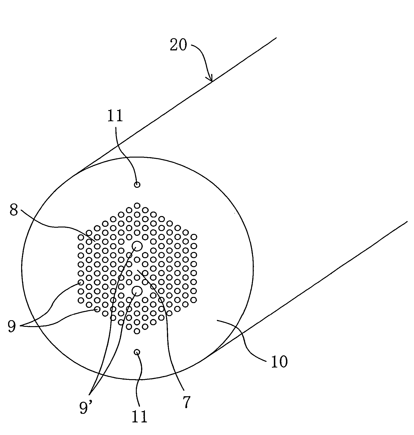
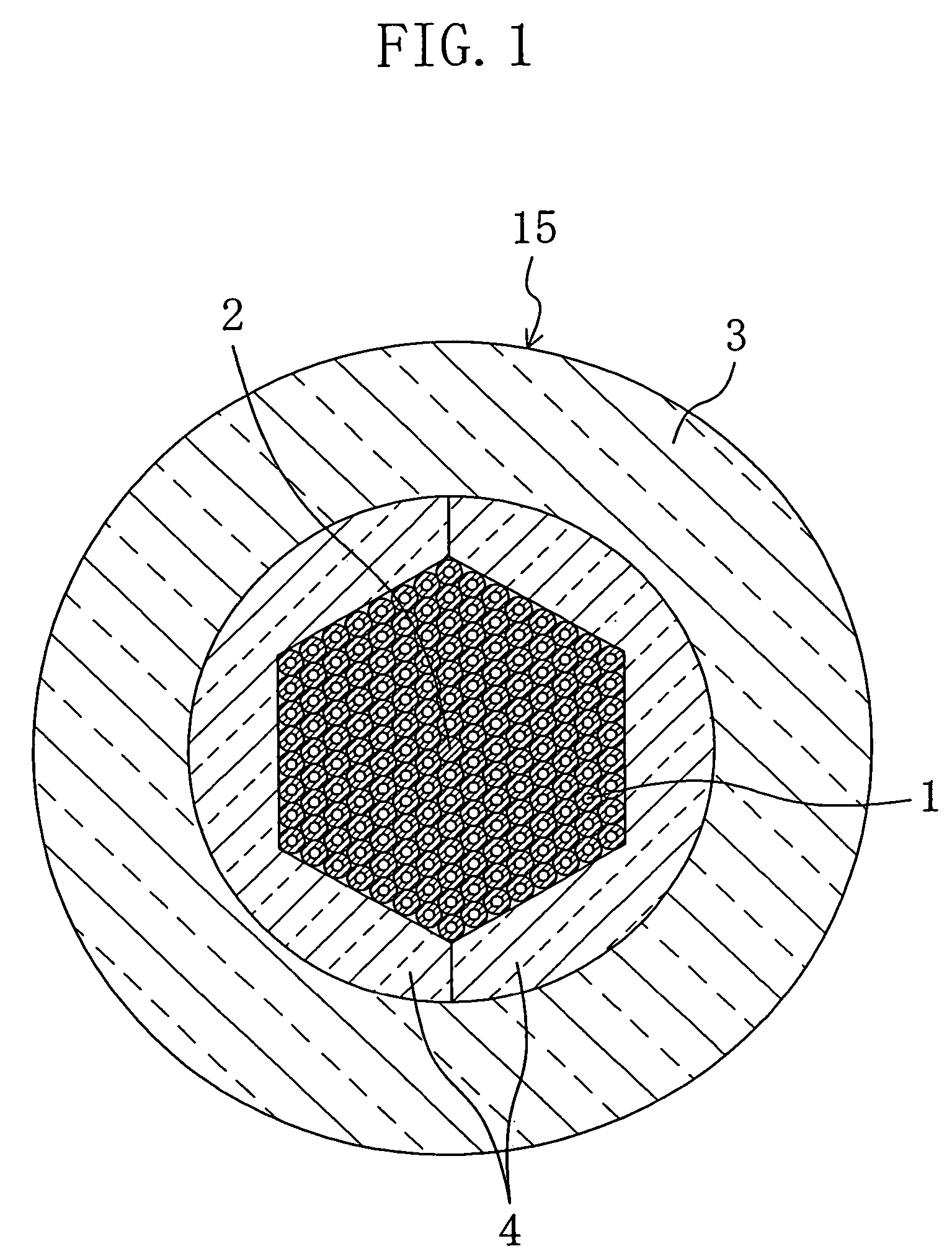
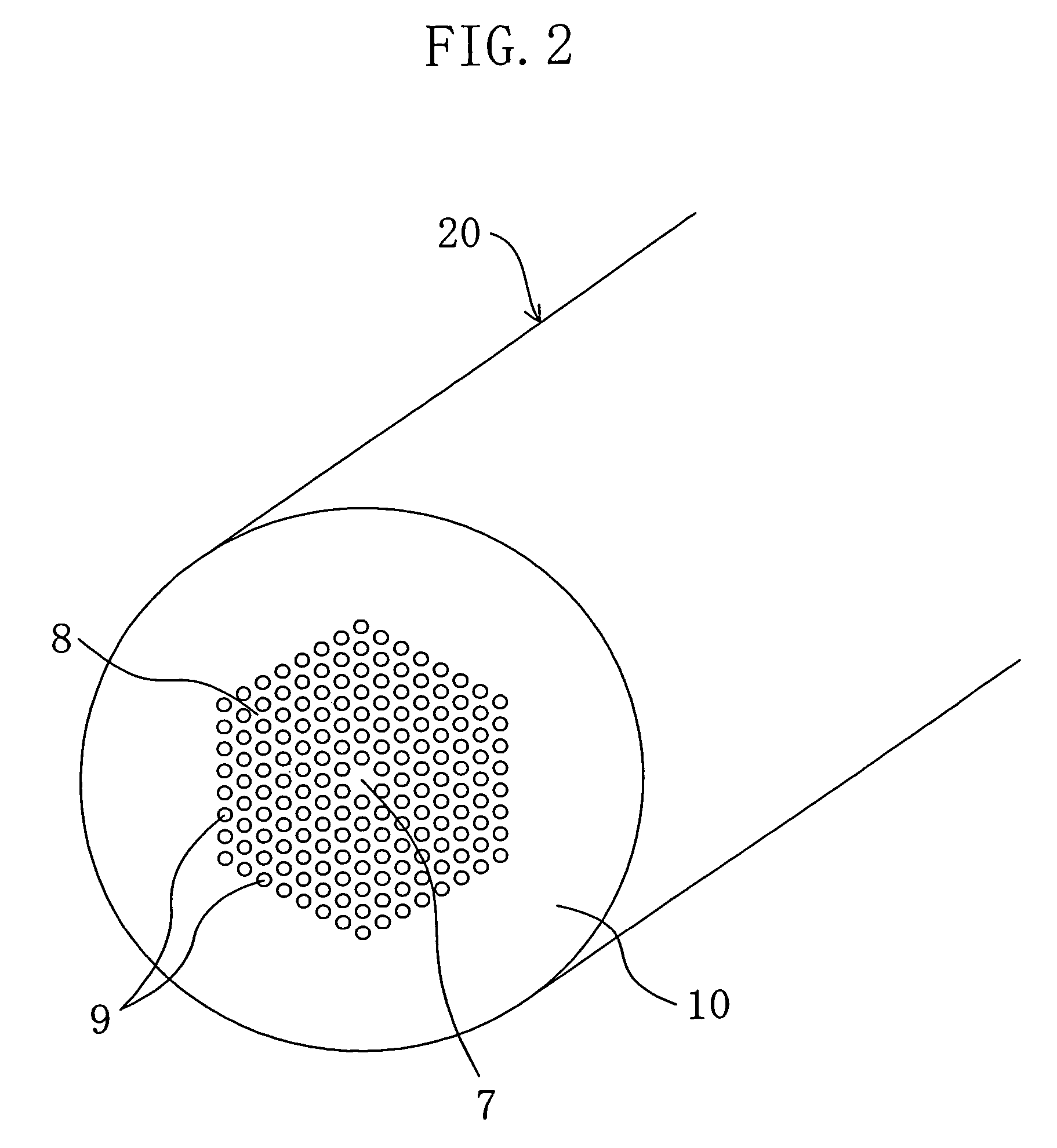
[0035]First, prepared are: a plurality of cylindrical quartz capillaries 1; a columnar core rod 2 which is made of quartz and has the same outer diameter and length as those of the capillaries 1; a large-diameter cylindrical support tube 3 which is made of quartz and has the same length as that of the capillaries 1 and a pair of spacer parts 4 made of quartz and has the same length as that of the support tube 3.

[0036]The spacer parts 4 are half parts of a cylindrical tube which are cut along the circumference direction. The inner wall surface of each of the spacer parts 4 is shaped to have a half of a regular hexagonal cross-sectional shape. In this embodiment, two spacer parts 4 are paired. The cross-sectional shape of the inner wall surface of the spacer 4 is so designed that among the capillaries 1 which are closest packed in the spacer 4 to form...

embodiment 2

[0052]Hereinafter, a step-by-step explanation is give of the method for manufacturing a PCF according to Embodiment 2.

[Preparation Step]

[0053]First, prepared are: a plurality of cylindrical, small-diameter capillaries 1 made of quartz; two cylindrical, quartz-made structure-indicating capillaries 6 of a small diameter which indicates the inner structure of the fiber; two cylindrical, quartz-made polarization maintaining capillaries 5 of a large diameter; a single columnar core rod 2 which is made of quartz and has the same diameter and length as those of the capillaries 1; a cylindrical, quartz-made support tube 3 which is shorter than the capillaries 1 and the core rod 2; and a pair of spacer parts 4 which are made of quartz and have the same length as that of the support tube 3.

[0054]The spacer parts 4 are halves of a cylindrical tube cut along the circumference direction and each of the spacer parts 4 has an inner wall surface which forms a half of a regular hexagonal cross-secti...


PUM

PropertyMeasurementUnit
lengthaaaaaaaaaa
degree of freedomaaaaaaaaaa
diameteraaaaaaaaaa

Abstract

A method for manufacturing a photonic crystal fiber including arranging a spacer formed of two or more spacer parts in a support tube such that the inner wall surface of the support tube has a substantially regular polygonal cross-sectional shape which allows closest packing of a core rod and a plurality of capillaries or the capillaries only; and forming a preform by packing in a support tube the core rod for forming a solid core and the capillaries for forming a cladding, or by providing a core space for forming a hollow core in a support tube and packing in the support tube a plurality of capillaries for forming the cladding; and drawing the preform into a fiber under heating.

Description

TECHNICAL FIELD[0001]The present invention relates to a method for manufacturing a photonic crystal fiber (hereinafter abbreviated as PCF) having a fiber body including a core and a cladding (porous part) which surrounds the core and has a plurality of pores extending along the core.BACKGROUND ART[0002]Optical fibers including a core and a cladding are well known as a light-transmitting medium. Among them, in recent years, attention has been paid to PCFs as promising optical fibers which allow communications in a novel wavelength band that have not been realized with conventional optical fibers and offer enhanced communication speed with reduced costs. The PCF includes a solid or hollow core which is provided in the center of the fiber and a cladding which surrounds the core and has a plurality of pores extending along the core. The PCF encloses light in the core surrounded by the cladding to transmit the light and controls the dispersion of light wavelength without restraint by cha...

Claims


Application Information

Patent Timeline
Patent Type & Authority Patents(United States)
IPC IPC(8): C03B37/028C03B37/012C03B37/027G02B6/00G02B6/02G02B6/024
CPCC03B37/01217C03B37/0122C03B37/02781G02B6/02328G02B6/02333G02B6/02347G02B6/02361G02B6/024C03B2203/14C03B2203/30C03B2203/42C03B2205/08G02B6/02357
Inventor KINOSHITA, TAKAHARUNAGAE, NOBUSADAFUKUDA, AKIHIKO
Owner MITSUBISHI CABLE IND LTD
Why Eureka
Try Eureka