Direct flux regulated permanent magnet brushless motor utilizing sensorless control

a permanent magnet, sensorless control technology, applied in the direction of motor/generator/converter stopper, electronic commutator, dynamo-electric converter control, etc., can solve the problems of difficult implementation of sensorless control utilizing this method, add cost and weight, etc., to increase saliency and easily identify the position of the rotor

Inactive Publication Date: 2010-11-30
HAMILTON SUNDSTRAND CORP
View PDF25 Cites 20 Cited by
  • Summary
  • Abstract
  • Description
  • Claims
  • Application Information

AI Technical Summary

Benefits of technology

[0006]In a disclosed embodiment of this invention, a rotor to be associated with a permanent magnet flux regulated motor is constructed such that it will have increased saliency. Essentially, the amount of ferric material through which the d axis and the q axis extend is made to be different, such that the difference in their inductances will also be more readily apparent, and a control will be able to more easily identify the position of the rotor.

Problems solved by technology

A sensor could be provided; however, a sensor would add to the cost and weight.
However, standard permanent magnet motor designs results in very small differences between the inductances along the d and q axes, and thus make implementation of sensorless control utilizing this method difficult.

Method used


Image

  • Direct flux regulated permanent magnet brushless motor utilizing sensorless control
  • Direct flux regulated permanent magnet brushless motor utilizing sensorless control
  • Direct flux regulated permanent magnet brushless motor utilizing sensorless control

Examples


Embodiment Construction

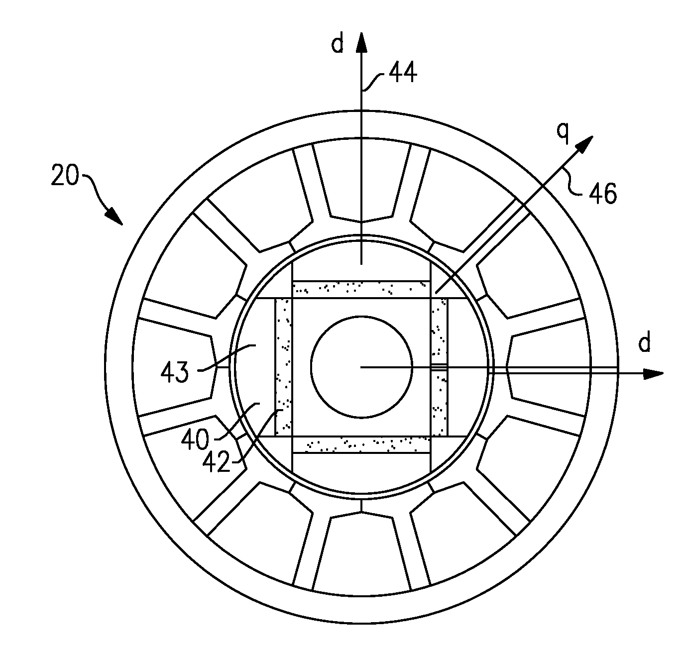
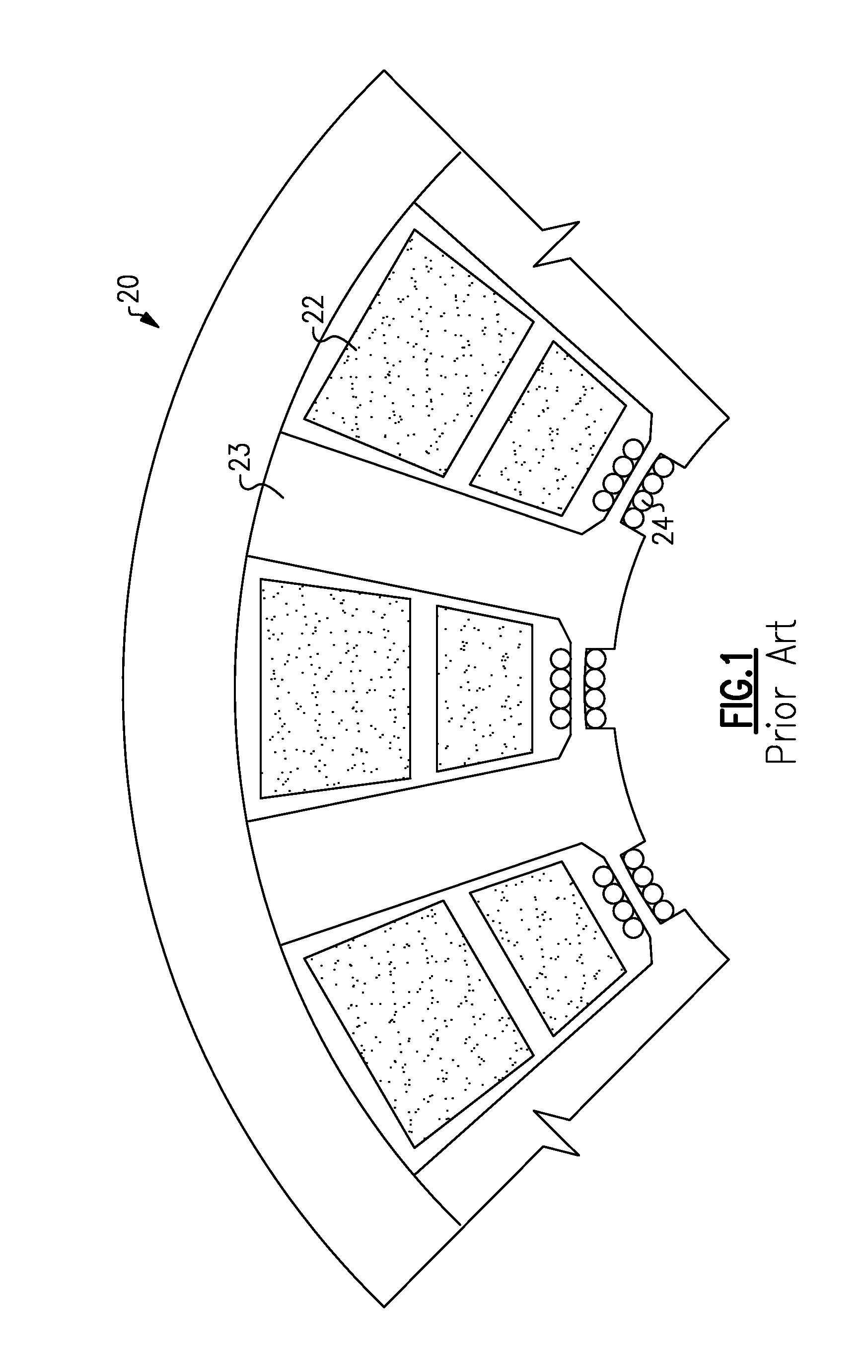
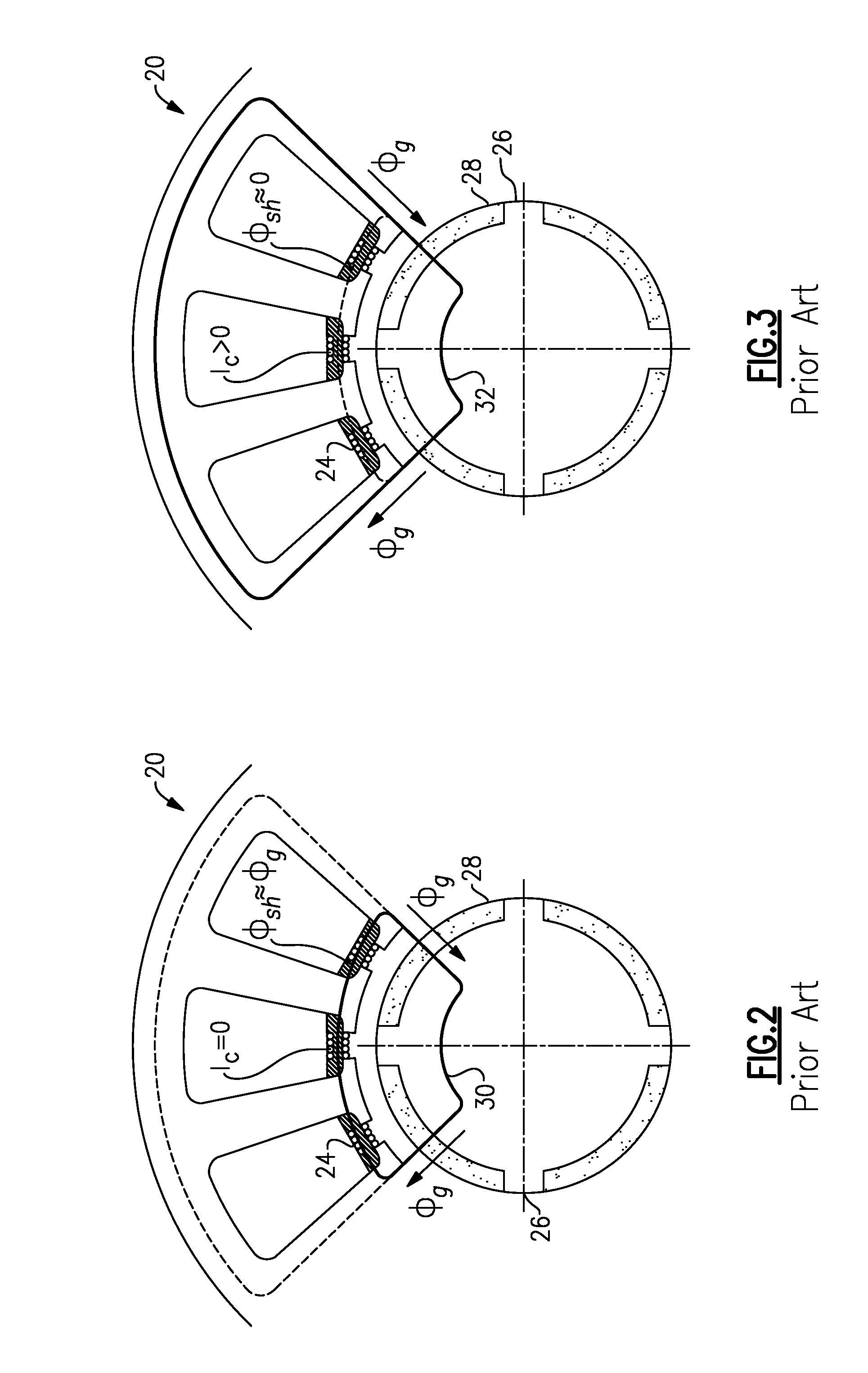
[0013]As shown in FIG. 1, in a known permanent magnet brushless motor, direct regulation of the magnetic flux is provided. A rotor, not shown in FIG. 1, is a permanent magnetic rotor, and the stator 20 is slotted. Stator slots are provided with wedges 22. Further, control coils 24 are provided. The control coils may receive a DC or an AC current. The coils 24 may be connected in series to create a control winding.

[0014]The slot wedges 22 behave as shunts for a magnetic flux produced by the permanent magnet motor. If the reluctance of the wedges is low, a portion of the magnetic flux is shunted by the wedges. While FIG. 1 shows a double layer stator winding or wedges 22, the proposed systems also contemplate a single layer. Stator teeth 23 are positioned between the wedges 22.

[0015]The wedges 22 may be made of a laminate ferromagnetic alloys or sintered magnetic powders. The magnetic wedges with the control coils can be inserted directly into conventional stator slots. Instead of rou...


PUM


Abstract

A permanent magnet rotor for use in a flux regulated permanent magnet brushless machine is constructed such that the inductance along the direct and quadrature axes is markedly different to provide sensorless position feedback for the rotor.

Description

BACKGROUND OF THE INVENTION[0001]This application relates to a permanent magnet flux regulated motor, wherein no sensor is necessary to provide position feedback of the location of the rotor.[0002]In the field of electric motors, permanent magnet motors are known, as are motors utilizing coils for their rotors. Recently, a permanent magnet brushless motor design has been developed, which uses direct flux regulation to provide better control. The stator may include slots which are closed by ferromagnetic wedges. The wedges are provided with control coils fed with current. By controlling the current through the control coils, the overall magnetic flux can be controlled.[0003]To use the overall control of magnetic flux, precise position feedback for the permanent magnet rotor is required. A sensor could be provided; however, a sensor would add to the cost and weight.[0004]Various sensorless control techniques are known, such as detection of back EMF, detection of the stator third harmo...

Claims


Application Information

Patent Timeline
Patent Type & Authority Patents(United States)
IPC IPC(8): H02P6/16
CPCH02K29/12H02P6/182H02K3/493
Inventor ROZMAN, GREGORY I.GIERAS, JACEK F.
Owner HAMILTON SUNDSTRAND CORP
Why Eureka
Try Eureka