LED device compensation method

a technology of led devices and compensation methods, which is applied in the direction of static indicating devices, instruments, semiconductor lamp usage, etc., can solve the problems of less efficient light emission, reduced display lifetime, and degradation of materials in light-emitting elements, so as to improve performance, limited display luminance, power use, and lifetime

Active Publication Date: 2010-12-07
GLOBAL OLED TECH
View PDF11 Cites 124 Cited by
  • Summary
  • Abstract
  • Description
  • Claims
  • Application Information

AI Technical Summary

Benefits of technology

[0016]An advantage of this invention is that it provides a compensation method that accommodates the need for improved performance with limited display luminance, power use, and lifetime.

Problems solved by technology

However, as the display is used, the materials in the light-emitting elements deteriorate and become less efficient at emitting light.
This deterioration reduces the lifetime of the display.
The differing materials may age at different rates, causing differential color aging and a display whose white point varies as the display is used.
Since displays are typically viewed in a single-stimulus environment, slow changes over time are acceptable, but large, noticeable changes are objectionable.
Since continuous, real-time compensations are usually not practical because they interfere with the operation of the LED device, most changes in LED device compensation are done periodically.
Hence, if an LED device output changes significantly during a single period, a noticeably objectionable compensation to the appearance of the display may result.
This technique reduces the perceptibility of compensation changes in an OLED display, but does not address the tradeoff between luminance, power, and lifetime inherent in such an OLED display.
The various prior-art aging compensation methods described above are useful in providing compensation, but do not teach methods for controlling or limiting the compensation.
Applicants have found that the maintenance of an LED device at a constant luminance may be impractical.
In any case, there is a limit to the amount of power that a display may dissipate, so that constant luminance may not be achieved.

Method used


Image

  • LED device compensation method
  • LED device compensation method
  • LED device compensation method

Examples


Embodiment Construction

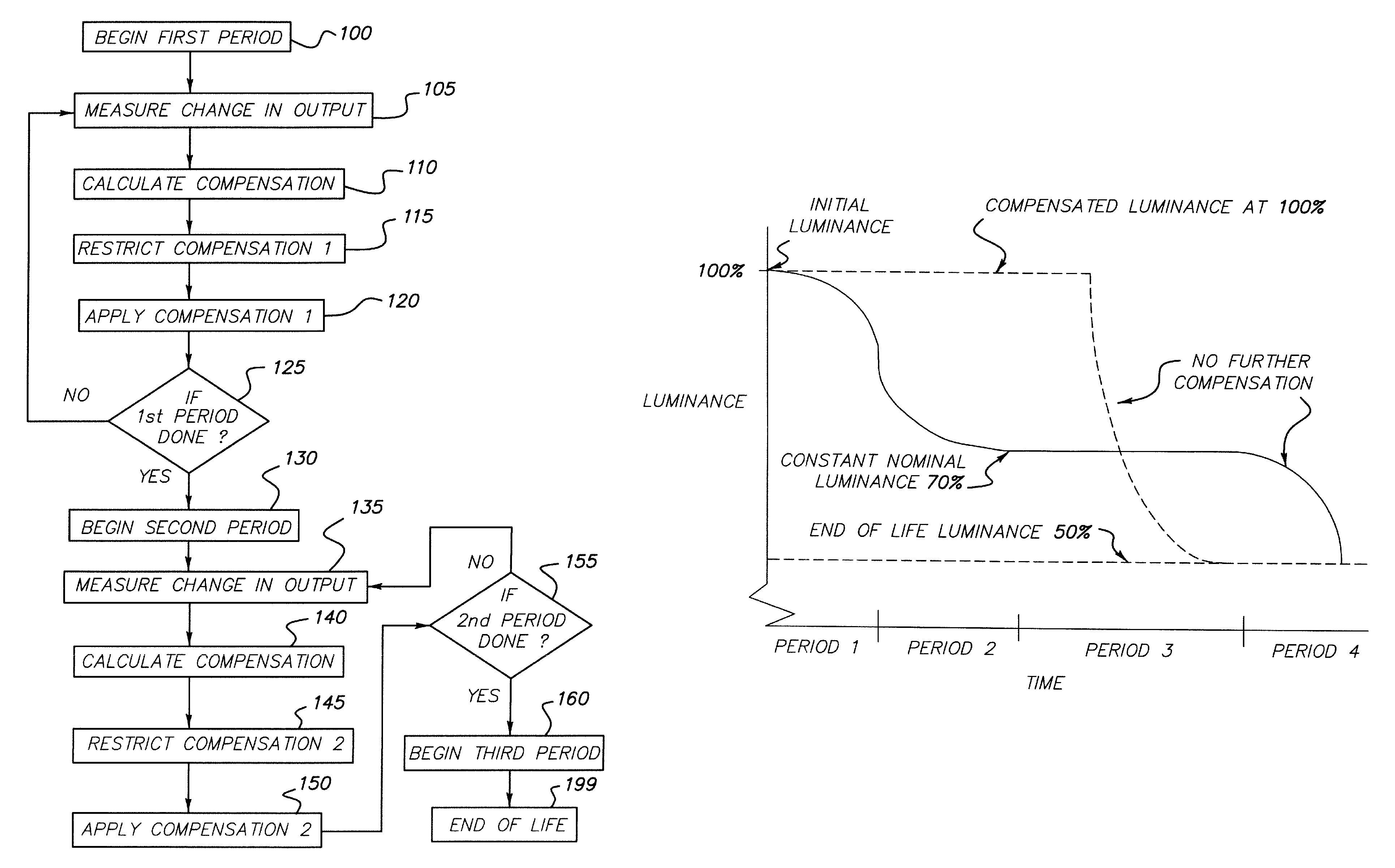
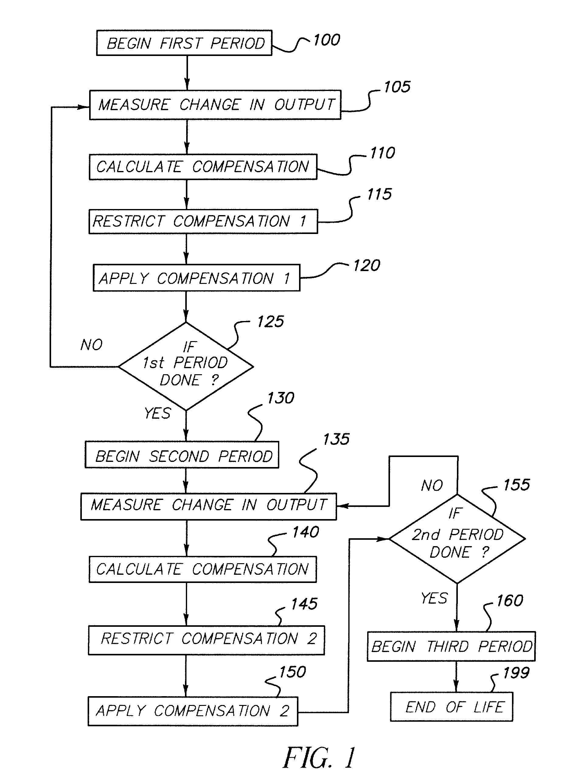
[0027]Referring to FIG. 1, according to one embodiment of the present invention, a method for controlling and compensating aging in an LED device comprises the steps of initializing 100 a first period, and measuring 105 the change in display output to calculate 110 a compensation signal. By employing a first algorithm to determine the desired compensation, the compensation may be restricted 115 to a first compensation during the first period and applied 120 to the LED device during the first period to effect a first compensation in the display output. The first period status may be tested 125 to determine whether to continue with the first period restriction by comparing the LED device performance to a first criterion. If it is determined to continue with the first period restriction, the process of measurement 105, compensation calculation 110, restricting 115 the compensation, and applying 120 the compensation is repeated. If not, a second period is begun 130. In this second perio...


PUM


Abstract

A method for controlling and compensating aging in an LED device includes measuring a performance change in light output of the LED device. The LED device is controlled with a first compensation algorithm derived from the measured performance change, during a first period, to effect a luminance change over time in the light output of the LED device. Subsequently, a second compensation algorithm, derived from the measured performance change, and different from the first compensation algorithm, during a second period, effects a second luminance change over time in the LED device's light output. The second luminance change over time in the second period is different from the first luminance change over time in the first period. Furthermore, the first and second periods together are less than the lifetime of the LED device.

Description

FIELD OF THE INVENTION[0001]The present invention relates to LED devices and more particularly to methods for compensating and controlling the aging of such devices.BACKGROUND OF THE INVENTION[0002]Solid-state light emitting diode (LED) image display devices are of great interest as a superior flat-panel display technology. These displays utilize current passing through thin films of organic or inorganic material to generate light. The color of light emitted and the efficiency of the energy conversion from current to light are determined by the composition of the thin-film material. Different materials emit different colors of light and may be employed in different light-emitting elements to form a full-color display. However, as the display is used, the materials in the light-emitting elements deteriorate and become less efficient at emitting light. This deterioration reduces the lifetime of the display. The differing materials may age at different rates, causing differential color...

Claims


Application Information

Patent Timeline
Patent Type & Authority Patents(United States)
IPC IPC(8): G09G3/30G09G3/10H05B44/00
CPCG09G3/32H05B33/0896H05B33/086G09G2320/043G09G2320/0633G09G2360/16G09G2360/145G09G2320/048H05B45/60H05B45/20Y02B20/30
Inventor COK, RONALD S.LEON, FELIPE A.LUDWICKI, JOHN E.
Owner GLOBAL OLED TECH
Why Eureka
Try Eureka