Method and an apparatus for capturing three-dimensional data of an area of space

a three-dimensional data and space technology, applied in the direction of distance measurement, reradiation, instruments, etc., can solve the problem that the forensic coverage of a crime scene requires further information which cannot be supplied by laser scanners, and achieve the effect of high measurement noise and accurate determination

Active Publication Date: 2010-12-07
FARO TECH INC
View PDF8 Cites 62 Cited by
  • Summary
  • Abstract
  • Description
  • Claims
  • Application Information

AI Technical Summary

Benefits of technology

[0023]In this embodiment, the body itself is surveyed in order to determine its center point as precisely as possible. The more accurately it is possible to determine the center point of the body, the more accurately it is possible to determine the orientation of the hidden channel.
[0024]In a preferred refinement of this embodiment, the body has a defined geometric shape and

Problems solved by technology

However, forensic coverage of a crime scene requires further info

Method used


Image

  • Method and an apparatus for capturing three-dimensional data of an area of space
  • Method and an apparatus for capturing three-dimensional data of an area of space
  • Method and an apparatus for capturing three-dimensional data of an area of space

Examples


Embodiment Construction

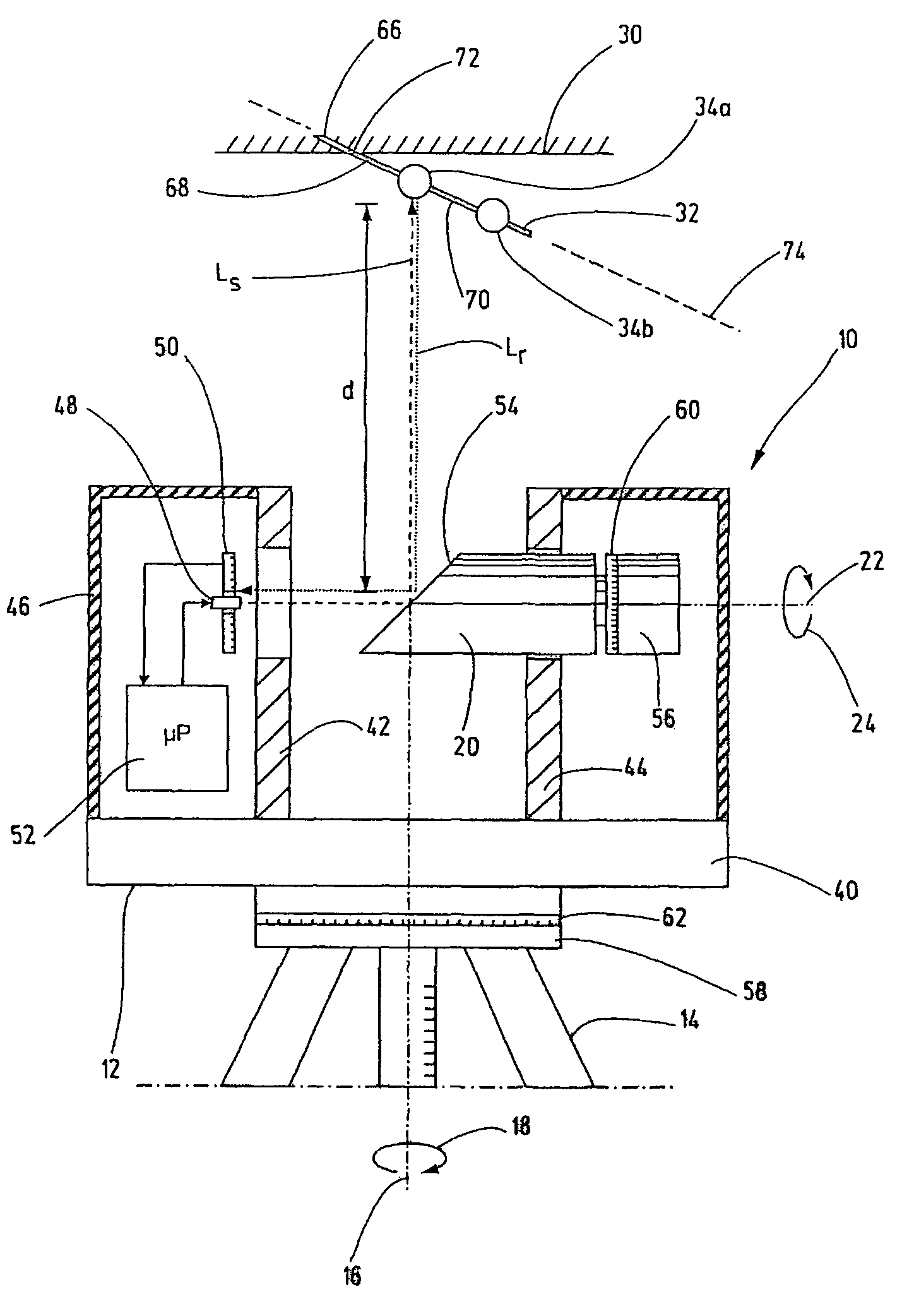
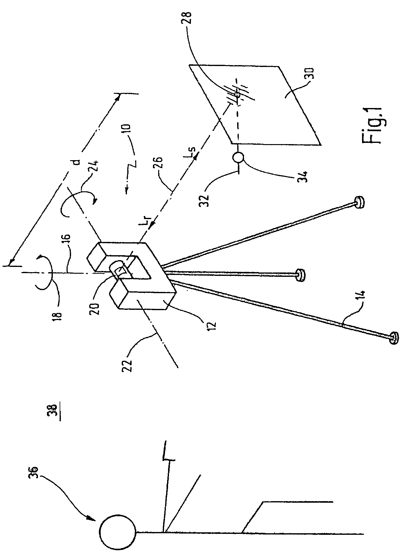
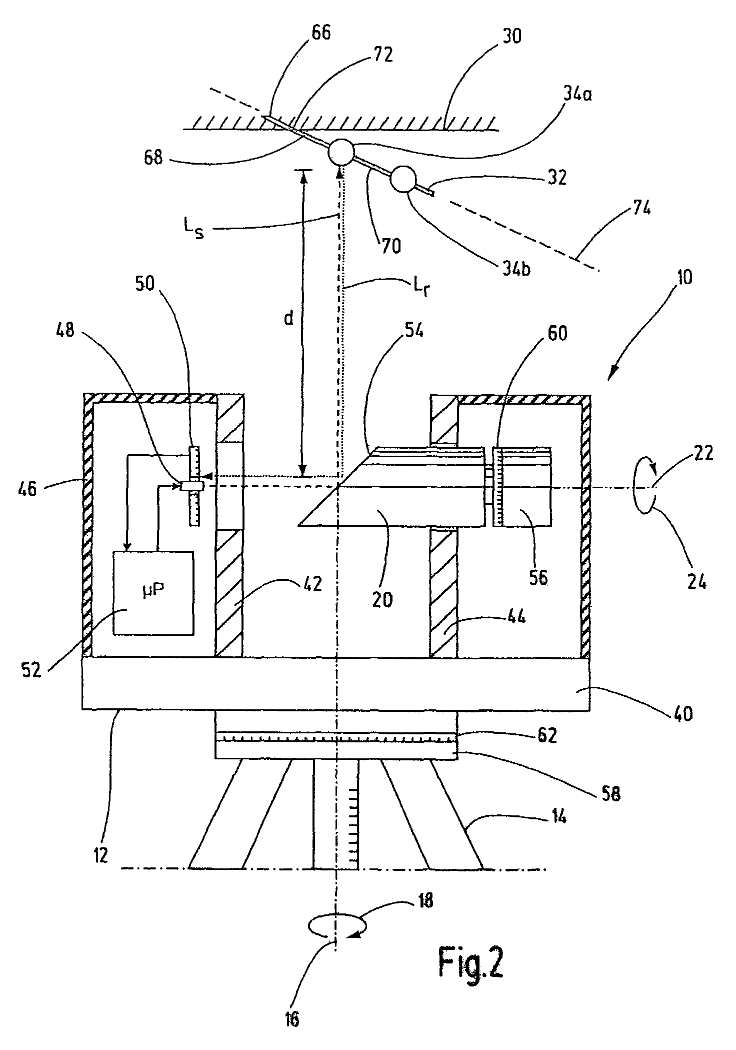
[0043]In FIG. 1, a laser scanner according to an embodiment of the present invention is designated by the reference number 10 overall. The laser scanner 10 has a measuring head 12 which is arranged on a tripod 14 in this case. The measuring head 12 can be rotated on the tripod 14 about a vertical axis 16 which is indicated by an arrow 18.

[0044]The measuring head 12 has an approximately U-shaped housing. Between the two housing legs, a rotor 20 is arranged which can be rotated about a horizontal axis 22 as is indicated by the arrow 24. The rotor 20 has an exit window from which a measuring beam Ls can emerge. The measuring beam Ls extends along a beam axis 26 to a measuring point 28 on an object 30. The measuring beam is reflected from the measuring point 28 and passes back to the measuring head 12 as reflected beam Lr where the reflected beam Lr encounters the rotor 20 and is detected by a detector, not shown here. From the time difference between sending out of the measuring beam L...


PUM


Abstract

In a method for capturing three-dimensional data of an area of space, a plurality of measuring beams (Ls) are sent out to a plurality of measuring points. A detector (50) receives a plurality of reflected beams (Lr) which are reflected by the measuring points (34a). A plurality of distances to the measuring points (34a, 34b) are determined as a function of the reflected beams (Lr). According to one aspect of the invention, at least one object (30) which comprises a hidden channel (66) having a visible entry opening (72) is located in the area of space. A rod-shaped element (32) is inserted into the channel (66) in such a manner that a free end (70) protrudes from the entry opening (72). A first distance to a first measuring point (34a) and a second distance to a second measuring point (34b) are determined. An orientation (74) of the hidden channel (66) is determined as a function of the first and the second distances.

Description

CROSS REFERENCE[0001]This is a U.S. national stage of application No. PCT / EP2007 / 005789, filed on 29 Jun. 2007. Priority under 35 U.S.C. §119(a) and 35 U.S.C. §365(b) is claimed from German Application No. 10 2006 031 580.4, filed 3 Jul. 2006, the disclosure of which is also incorporated herein by reference.BACKGROUND OF THE INVENTION[0002]The present invention relates to a method for capturing three-dimensional data of an area of space, comprising the steps of:[0003]providing a laser scanner having a transmitter and a receiver,[0004]sending out a plurality of measuring beams by means of the transmitter to a plurality of measuring points in the area of space,[0005]receiving a plurality of reflected beams which are reflected by the measuring points, and[0006]determining a plurality of distances to the plurality of measuring points as a function of the reflected beams.[0007]The invention also relates to an apparatus for capturing three dimensional data of an area of space, comprising ...

Claims


Application Information

Patent Timeline
IPC IPC(8): G01C3/08G01C1/00G01S17/89
CPCF41J5/00G01C15/002G01S17/08G01S17/89G01C15/02G01C15/06
Inventor GITTINGER, JUERGENBECKER, BERND-DIETMARBECKER, REINHARD
Owner FARO TECH INC
Why Eureka
Try Eureka