Propulsion system with integrated rocket accelerator

a propulsion system and accelerator technology, applied in the direction of rocket engine plants, machines/engines, composite engine plants, etc., can solve the problems of lack of effective specific impulse, lack of integrated vehicle efficiency or effective specific impulse, and performance of airbreathing flowpaths, so as to achieve low vehicle base drag, high thrust, and moderate efficiency.

Active Publication Date: 2010-12-14
AEROJET ROCKETDYNE INC
View PDF4 Cites 2 Cited by
  • Summary
  • Abstract
  • Description
  • Claims
  • Application Information

AI Technical Summary

Benefits of technology

[0005]Accordingly, it is an object of the present invention to provide an improved propulsion system which provides a more efficient vehicle-level solution to a boost phase by combining the ability to provide high thrust with moderate efficiency and low vehicle base drag without compromising the high speed propulsion system performance.

Problems solved by technology

External rockets, although capable of providing high thrust levels beneficial to rapid acceleration and minimizing fuel burn, lack integrated vehicle efficiency or effective specific impulse (thrust minus drag divided by propellant flow rate).
This is due to the fact that the airbreathing flowpath is not performing optimally during the low Mach number trajectory phase with inherent large aft facing areas contributing to large vehicle base drag.
Although base drag is reduced over external rocket integrations, the scramjet nozzle pressure ratio is typically too low for the nozzle to pressurize appreciably resulting in the requirement for other base or external burning means to reduce drag.

Method used


Image

  • Propulsion system with integrated rocket accelerator
  • Propulsion system with integrated rocket accelerator
  • Propulsion system with integrated rocket accelerator

Examples


Embodiment Construction

)

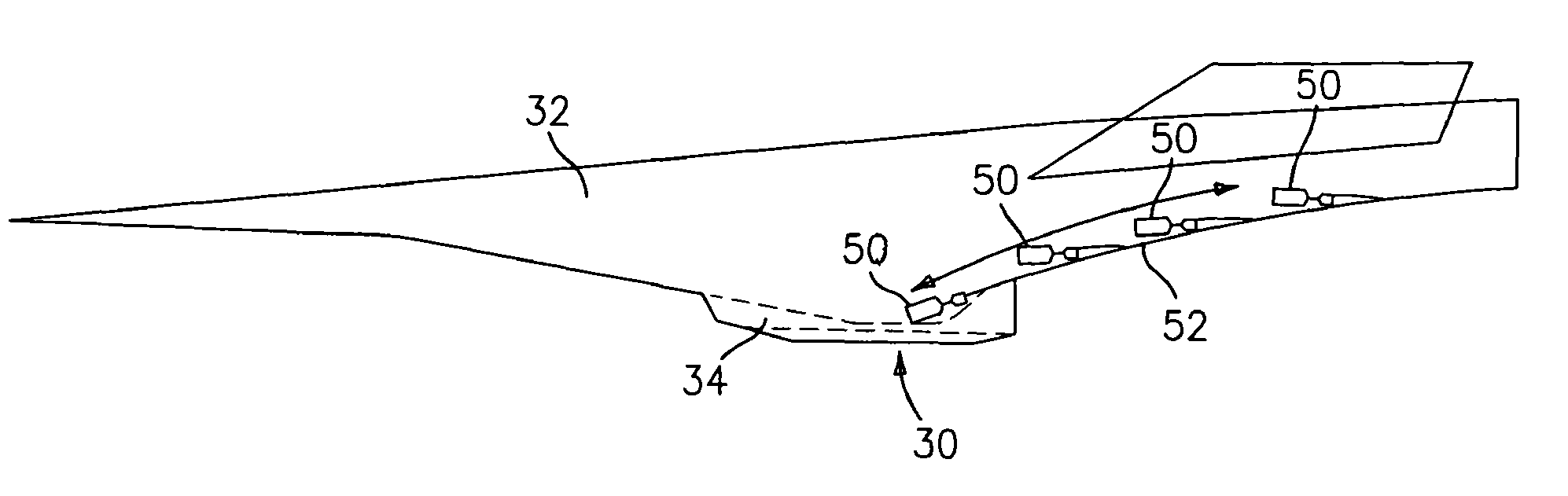
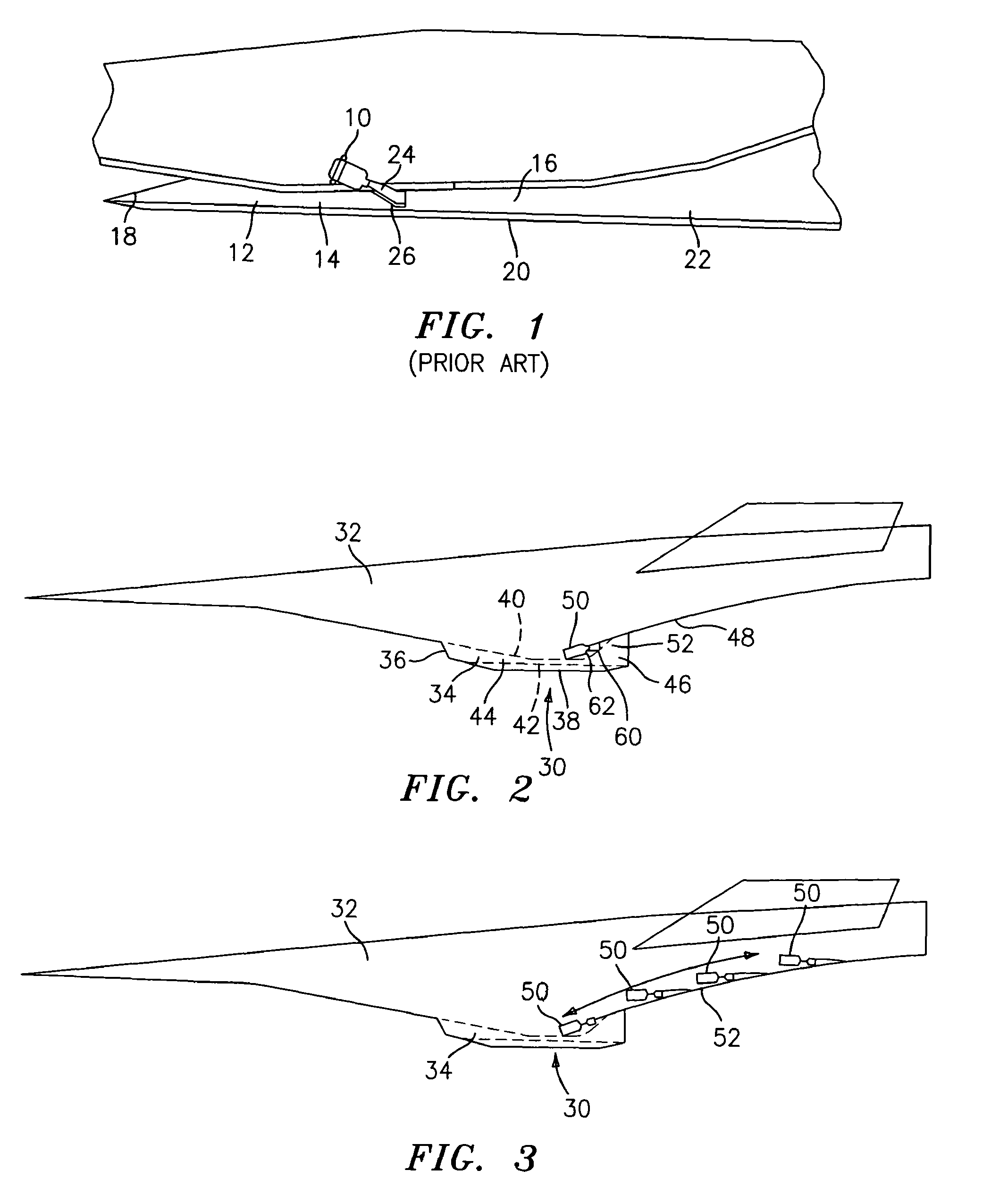
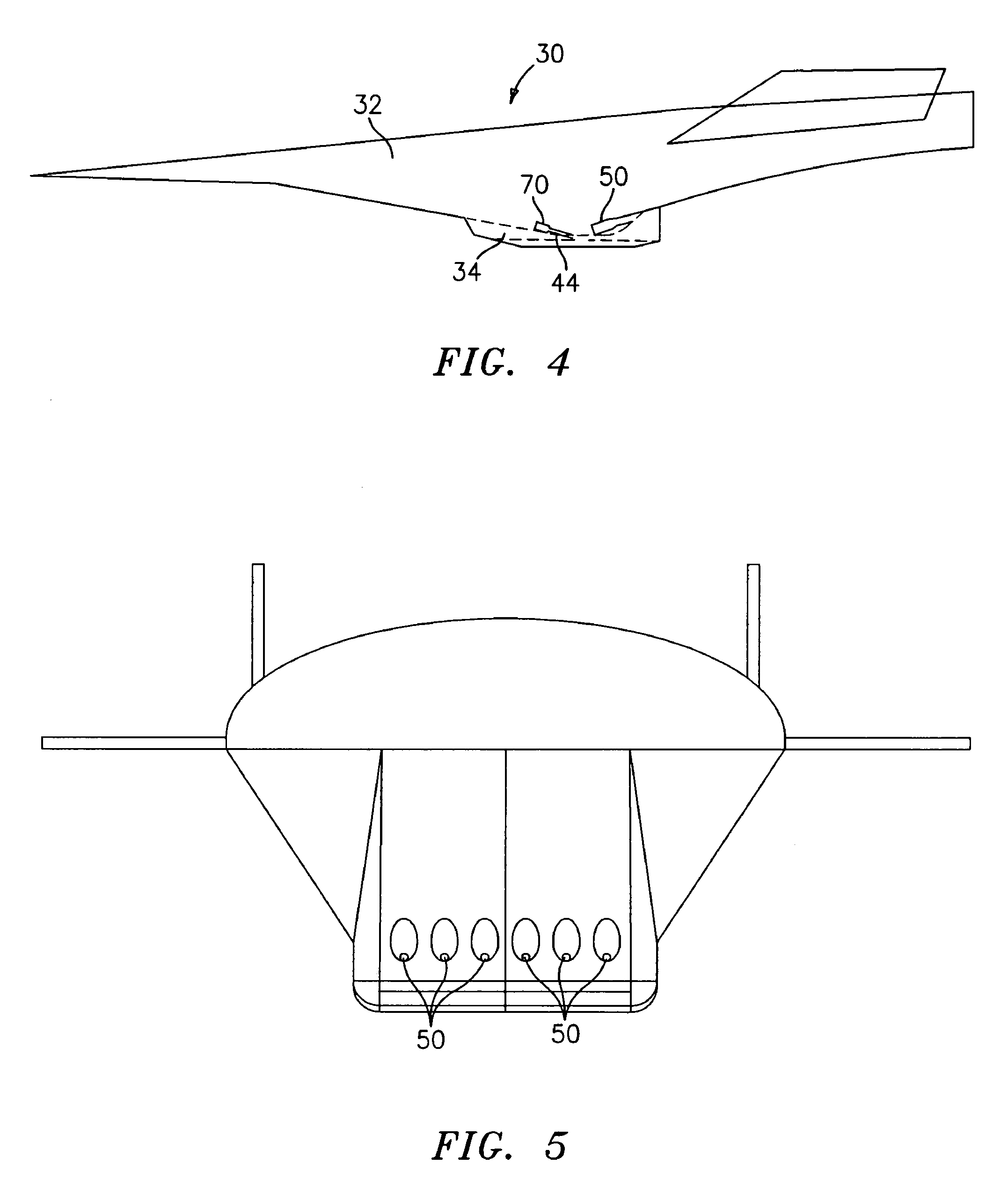
[0015]FIG. 2 illustrates a propulsion system 30 incorporated into a vehicle 32. The propulsion system 30 includes an airframe-integrated, hydrocarbon fueled, airbreathing engine 34 such as a ramjet or a scramjet. The engine 34 has an inlet 36, an outer cowl 38, an interior wall structure 40, and a flow path 42 determined by the contour of the interior wall structure 40 and the outer cowl 38. The flow path 42 includes a throat region 44, and a nozzle 46. The nozzle 46 is in part formed by the contour of an aft-body 48.

[0016]In accordance with the present invention, as shown in FIG. 2, one or more hydrocarbon propellant rockets 50 are incorporated into the propulsion system 30 in such a manner as to take advantage of the contour of the aft-body 48 as a high area ratio self-compensating nozzle. While only one rocket 50 is shown in FIG. 2, there may be in actuality a plurality of rockets 50 transversely aligned as shown in FIG. 5 across the width of the nozzle 46. As shown in FIG. 2, e...


PUM


Abstract

The present invention relates to a propulsion system for a vehicle. The propulsion system has an airframe integrated hydrocarbon fueled airbreathing engine, such as a ramjet or a scramjet. The propulsion system further has at least one rocket positioned so as to use the aft body contour of the vehicle directly for flow expansion. In a preferred embodiment, a plurality of rockets are arrayed across the width of the engine nozzle.

Description

BACKGROUND OF THE INVENTION[0001]The present invention relates to an improved propulsion system for a vehicle, such as an aircraft, with the propulsion system comprising an engine having an integrated hydrocarbon propellant rocket system positioned with respect to the engine so as to take advantage of the aft-body contour as a high area ratio self-compensating nozzle.[0002]Existing airframe-integrated hydrocarbon fueled ramjet / scramjet engine concepts are designed to operate at flight velocities beginning at about Mach 4 and provide vehicle acceleration and cruise capabilities to as high as Mach 8. To provide the initial acceleration or boost to Mach 4, a variety of propulsion systems have been proposed including external solid or liquid rockets as well as ejector ramjets also referred to as Rocket Based Combined Cycle (RBCC) engines.[0003]External rockets, although capable of providing high thrust levels beneficial to rapid acceleration and minimizing fuel burn, lack integrated veh...

Claims


Application Information

Patent Timeline
Patent Type & Authority Patents(United States)
IPC IPC(8): F02K7/18F02K1/00
CPCB64C30/00B64D27/023Y02T90/44Y02T90/40
Inventor BECKEL, STEPHEN A.BLEVINS, JAMES D.VERDI, THOMAS
Owner AEROJET ROCKETDYNE INC
Why Eureka
Try Eureka