Ultra-low noise MEMS piezoelectric accelerometers

a piezoelectric accelerometer and ultra-low noise technology, applied in the field of microelectromechanical system sensing structures, can solve the problems that the vibration sensor available on the market cannot meet all of these applications, the state of the art, and the inability to meet the functions of tools

Inactive Publication Date: 2010-12-14
INTEL CORP
View PDF2 Cites 4 Cited by
  • Summary
  • Abstract
  • Description
  • Claims
  • Application Information

AI Technical Summary

Problems solved by technology

Excess vibrations in the environment may cause malfunction of tools.
However, state of the art vibration sensors available on the market cannot satisfy all of these applications.
Highly sensitive vibration sensors with a noise floor of approximately 1 μg / sqrt(Hz) at approximately 10 Hz are large in size, making them difficult to use in many applications requiring a small form factor and light weight, such as monitoring robotic arms.
They are also prohibitively expensive for large-scale sensor network applications that are becoming increasingly important.
Currently MEMS based sensors of small sizes are not sensitive enough at low frequency ranges.

Method used


Image

  • Ultra-low noise MEMS piezoelectric accelerometers
  • Ultra-low noise MEMS piezoelectric accelerometers
  • Ultra-low noise MEMS piezoelectric accelerometers

Examples


Embodiment Construction

[0020]In the following description, various aspects of the present invention will be described. For purposes of explanation, specific configurations and details are set forth in order to provide a thorough understanding of the present invention. However, it will be apparent to one skilled in the art that the present invention may be practiced without the specific details presented herein. Furthermore, well-known features may be omitted or simplified in order not to obscure the present invention. Various examples are given throughout this description. These are merely descriptions of specific embodiments of the invention. The scope of the invention is not limited to the examples given.

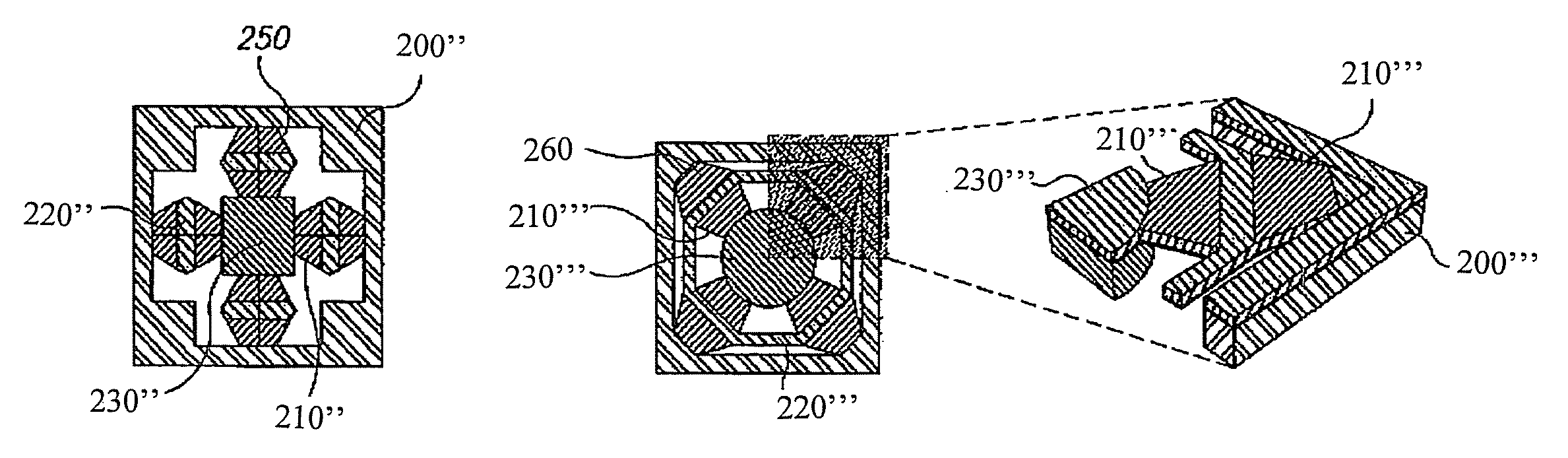
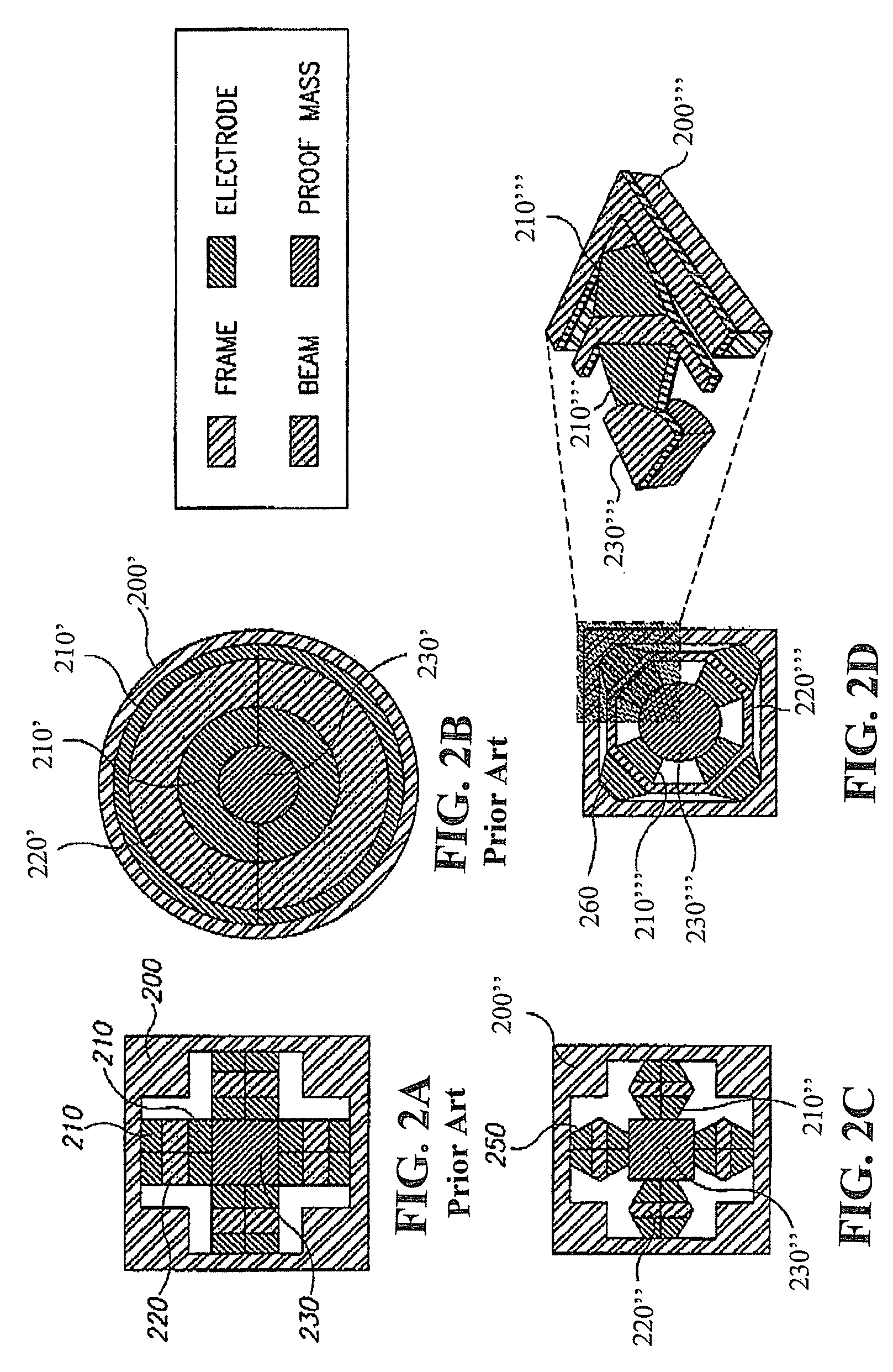
[0021]One embodiment of the present invention includes a sensing structure including for example a frame; a proof mass; and a plurality of arms, each arm including an electrode having two ends, wherein a first of the two ends is attached to said frame and a second of the two ends is attached to said pro...


PUM


Abstract

Sensing structures are provided which are designed using non-conventional designs. These sensing structures have improved sensitivity and noise floor at low frequencies.

Description

FIELD OF THE INVENTION[0001]The present invention generally relates to sensing structures. In particular, the present-invention relates to microelectromechanical systems sensing structures.BACKGROUND OF THE INVENTION[0002]Vibration sensors are used for monitoring structures (e.g., buildings, bridges), vehicles (e.g., ships, airplanes, autos, trains) and machines. In fabrication facilities, many tools, particularly high precision lithographic and analytical tools, require real time monitoring for any abnormal vibration signals. Excess vibrations in the environment may cause malfunction of tools. Vibration signals originating from the tools themselves may serve as an indication that the tools require maintenance. Accurate in-line monitoring could significantly reduce down time and its associated cost. Machine vibration monitoring and diagnostics require a very low noise floor at low frequencies because the amplitude of vibrations, in terms of acceleration that is produced, is very sma...

Claims


Application Information

Patent Timeline
Patent Type & Authority Patents(United States)
IPC IPC(8): G01P15/09
CPCB81B3/0086G01H11/08G01P15/0922G01P15/18B81B2201/0235B81B2203/04G01P2015/084
Inventor WANG, LI-PENGGERFERS, FRIEDELHE, MING-YUAN
Owner INTEL CORP
Why Eureka
Try Eureka