Method of and an apparatus for in situ ultrasonic rail inspection of a railroad rail

a technology of ultrasonic rail and in situ inspection, which is applied in the direction of instruments, specific gravity measurement, measurement devices, etc., can solve the problems of non-critical and critical defects, defects, vertical sheer or split head defects,

Active Publication Date: 2010-12-14
SPERRY RAIL HLDG
View PDF13 Cites 29 Cited by
  • Summary
  • Abstract
  • Description
  • Claims
  • Application Information

AI Technical Summary

Problems solved by technology

The flaws may include both non-critical and critical defects, for example, transverse defects, vertical sheer or split head defects, and horizontal sheer or split head defects.
However, in time, even non-critical flaws may abscess or degrade into critical defects, and new flaws will arise.
If the flaws are left unattended, the resulting defects could lead to a range of problems including catastrophic failure and train derailment.
Catastrophic or even lesser failures present a financial, health and safety risk to the railway industry, transported goods and personnel, as well as surrounding homes and businesses.
Additionally, sleds are more sensitive to imperfections and flaws on the running surface of the rail.
Wheel designs suffer from acoustic reverberation (noise) caused by acoustic reflections from the surface walls of the tire.
The noise reduces the sensitivity of the apparatus following each acoustic emission.
Further, both designs suffer from the limitations of known transducer technologies and configurations.
Some acoustic transducer designs emit ultrasonic beams in a substantially vertical direction, which identifies some flaws in the web of the rail while lacking sensitivity to flaws in the internal portions of the head of the rail.
The designs identify some additional flaws in the rail, particularly in the side of the head of the rail.
Still other acoustic transducer designs include more elaborate transducer assemblies with additional beam paths, but still have limited ability to identify flaws in the internal portion of the head of the rail.

Method used


Image

  • Method of and an apparatus for in situ ultrasonic rail inspection of a railroad rail
  • Method of and an apparatus for in situ ultrasonic rail inspection of a railroad rail
  • Method of and an apparatus for in situ ultrasonic rail inspection of a railroad rail

Examples


Embodiment Construction

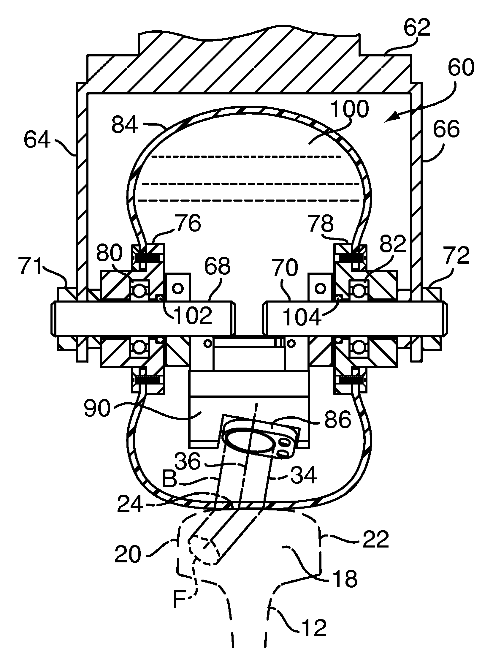
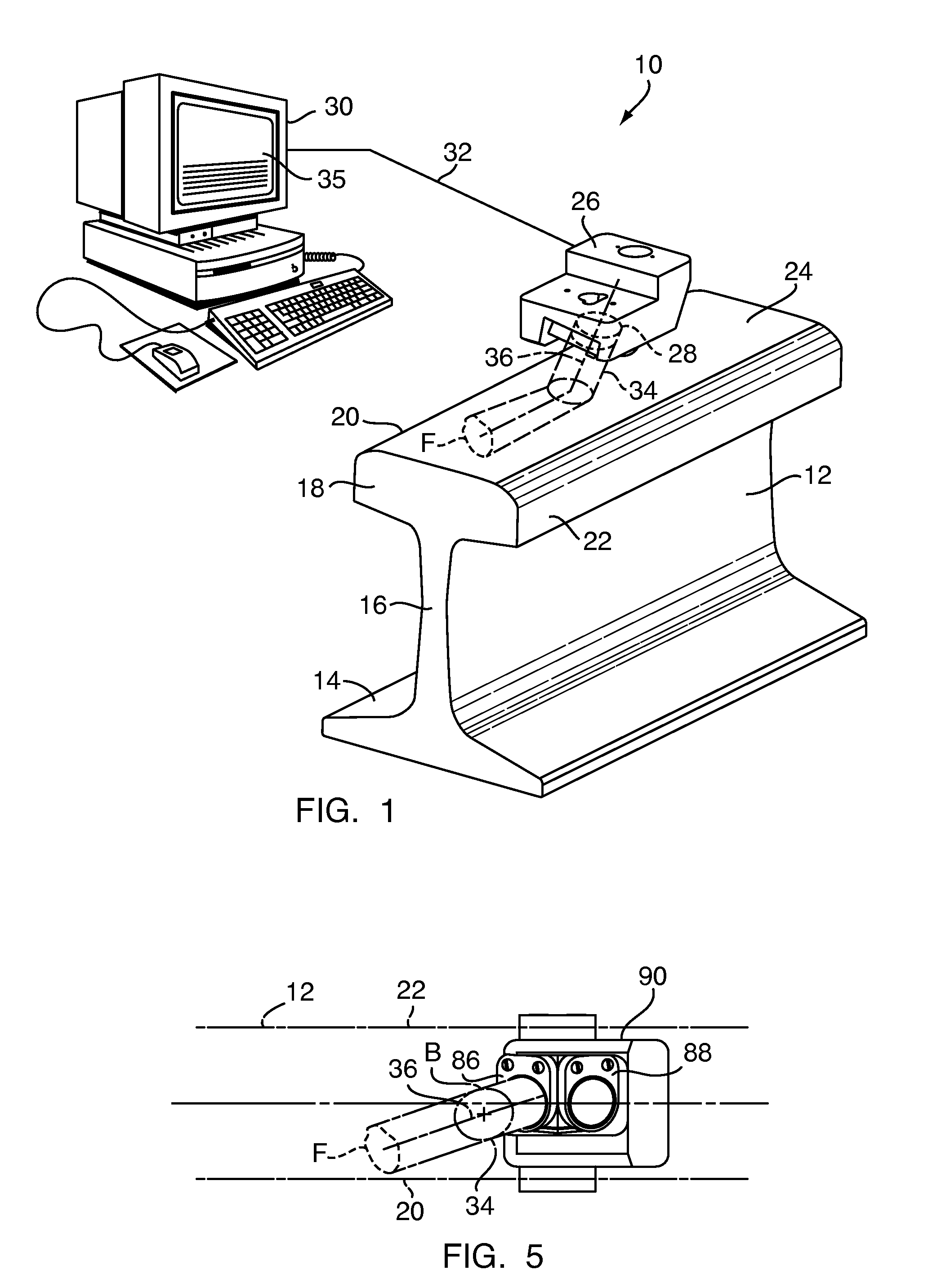
[0020]FIG. 1 shows an ultrasonic railroad rail inspection system 10 that inspects a railroad rail 12 for internal structural flaws or defects. The rail has a typical, known rail design with a base 14, a central web 16, and head 18. The head is shaped with a gauge side 20, a field side 22, and a upper running surface 24. For purposes of orientation, the directional axes of the railroad rail 12 are defined as the vertical longitudinal plane which extends vertically along the path of travel on the rail at the center or median of the rail, the horizontal longitudinal plane which extends horizontally along the path of travel on the rail, and the transverse plane which extends vertically and perpendicular to the path of travel on the rail.

[0021]The system 10 includes flaw detector or sensor 26 containing one or more ultrasonic transducers 28, which are generally transmitter-receiver transducers, that are controlled by a central processing unit 30 connected to the transducer by a cable 32 ...


PUM

PropertyMeasurementUnit
angleaaaaaaaaaa
diameteraaaaaaaaaa
angleaaaaaaaaaa

Abstract

An ultrasonic railroad rail inspection system, apparatus and method for in situ rail inspection including a wheel assembly containing a fluid-filled tire and an ultrasonic transducer mounted within the wheel assembly. The transducer is supported in the tire such that the ultrasonic beam generated by the transducer has a beam axis that intersects a head of a railroad rail at a position offset from the longitudinal median plane of the rail to the side of the head penetrated by the ultrasonic beam. The ultrasonic beam is reflected by flaws in the rail in the form of echoes. The echoes return to the transducer identifying the location of flaws.

Description

FIELD OF THE INVENTION[0001]The present invention relates, in general, to a non-destructive testing method and apparatus for certain predetermined types of undesirable flaws or defects which may be present in the rails of a railroad track. More particularly, the present invention relates to a mobile and durable type apparatus that will ultrasonically detect flaws in the rail, identify the location of the flaw when detected, and record the location of the detected flaws for possible future repair, or more likely, rail replacement. More specifically, the present invention relates to a relatively fast and sensitive method and apparatus for detecting, identifying, and recording the location of the flaws that are detected by the apparatus as the apparatus travels over the rail in situ.BACKGROUND OF THE INVENTION[0002]It is well recognized in the railway industry that, either through manufacturing processes or through natural environmental processes and normal use, rails of a railroad tra...

Claims


Application Information

Patent Timeline
Patent Type & Authority Patents(United States)
IPC IPC(8): G01N29/265G01N29/24G01N29/06
CPCG01N29/043G01N29/2493G01N29/28G01N2291/044G01N2291/2623
Inventor HAVIRA, ROBERT MARK
Owner SPERRY RAIL HLDG
Why Eureka
Try Eureka