
Method and apparatus for collecting drill bit performance data

a technology of drill bit and performance data, applied in the field of drill bit, can solve the problems of affecting drilling operations, affecting drilling operations, and relatively infrequent failure, and affecting drilling operations

Active Publication Date: 2010-12-14
BAKER HUGHES INC
View PDF62 Cites 30 Cited by
  • Summary
  • Abstract
  • Description
  • Claims
  • Application Information

AI Technical Summary

Problems solved by technology

The oil and gas industry expends sizable sums to design cutting tools, such as downhole drill bits including roller cone rock bits and fixed cutter bits, which have relatively long service lives, with relatively infrequent failure.
The loss of a roller cone or a polycrystalline diamond compact (PDC) from a fixed cutter bit during drilling operations can impede the drilling operations and, at worst, necessitate rather expensive fishing operations.
These premature replacements of downhole drill bits are expensive, since each trip out of the well prolongs the overall drilling activity, and consumes considerable manpower, but are nevertheless done in order to avoid the far more disruptive and expensive process of, at best, pulling the drillstring and replacing the bit or fishing and sidetrack drilling operations necessary if one or more cones or compacts are lost due to bit failure.
Unfortunately, these subs cannot provide actual data for what is happening operationally at the bit due to their physical placement above the bit itself.
Data gathered from a sub this far away from the bit may not accurately reflect what is happening directly at the bit while drilling occurs.
Often, this lack of data leads to conjecture as to what may have caused a bit to fail or why a bit performed so well, with no directly relevant facts or data to correlate to the performance of the bit.
However, data gathering, storing, and reporting from these systems has been limited.
In addition, conventional data gathering in drill bits has not had the capability to adapt to drilling events that may be of interest in a manner allowing more detailed data gathering and analysis when these events occur.

Method used


Image

  • Method and apparatus for collecting drill bit performance data
  • Method and apparatus for collecting drill bit performance data
  • Method and apparatus for collecting drill bit performance data

Examples


Embodiment Construction

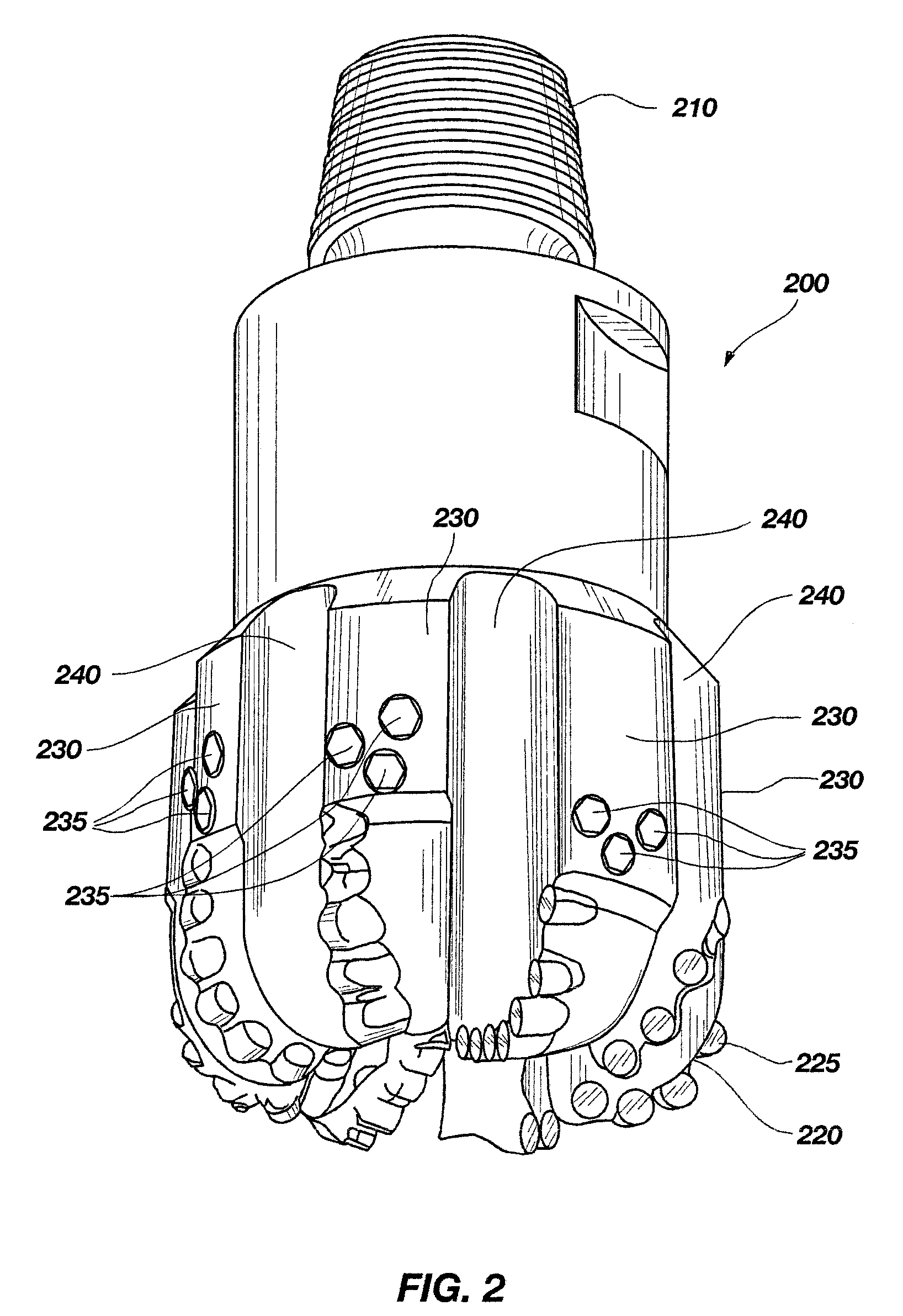
[0039]The present invention includes a drill bit and an electronics module disposed within the drill bit for analysis of data sampled from physical parameters related to drill bit performance using a variety of adaptive data sampling modes.

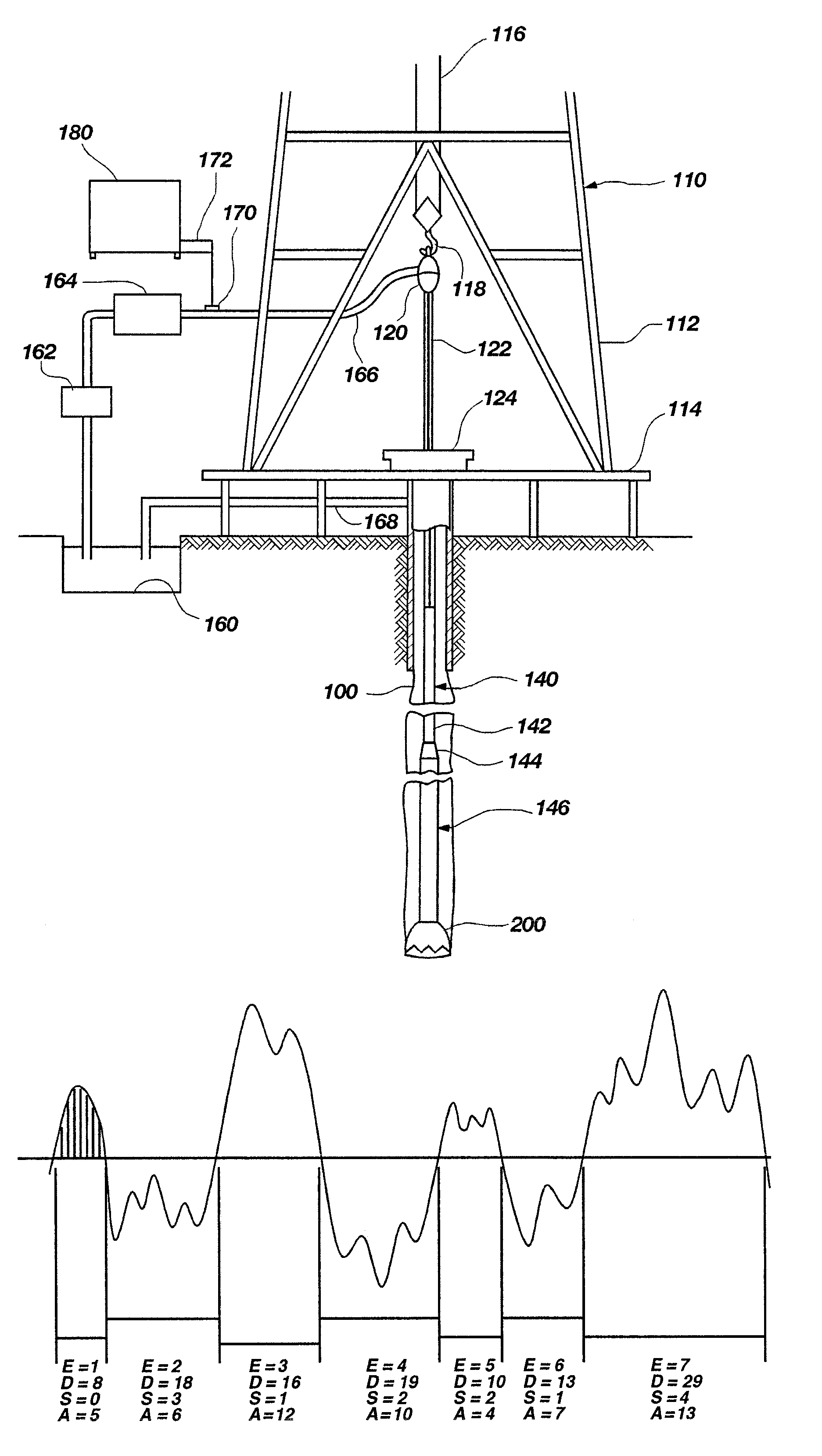
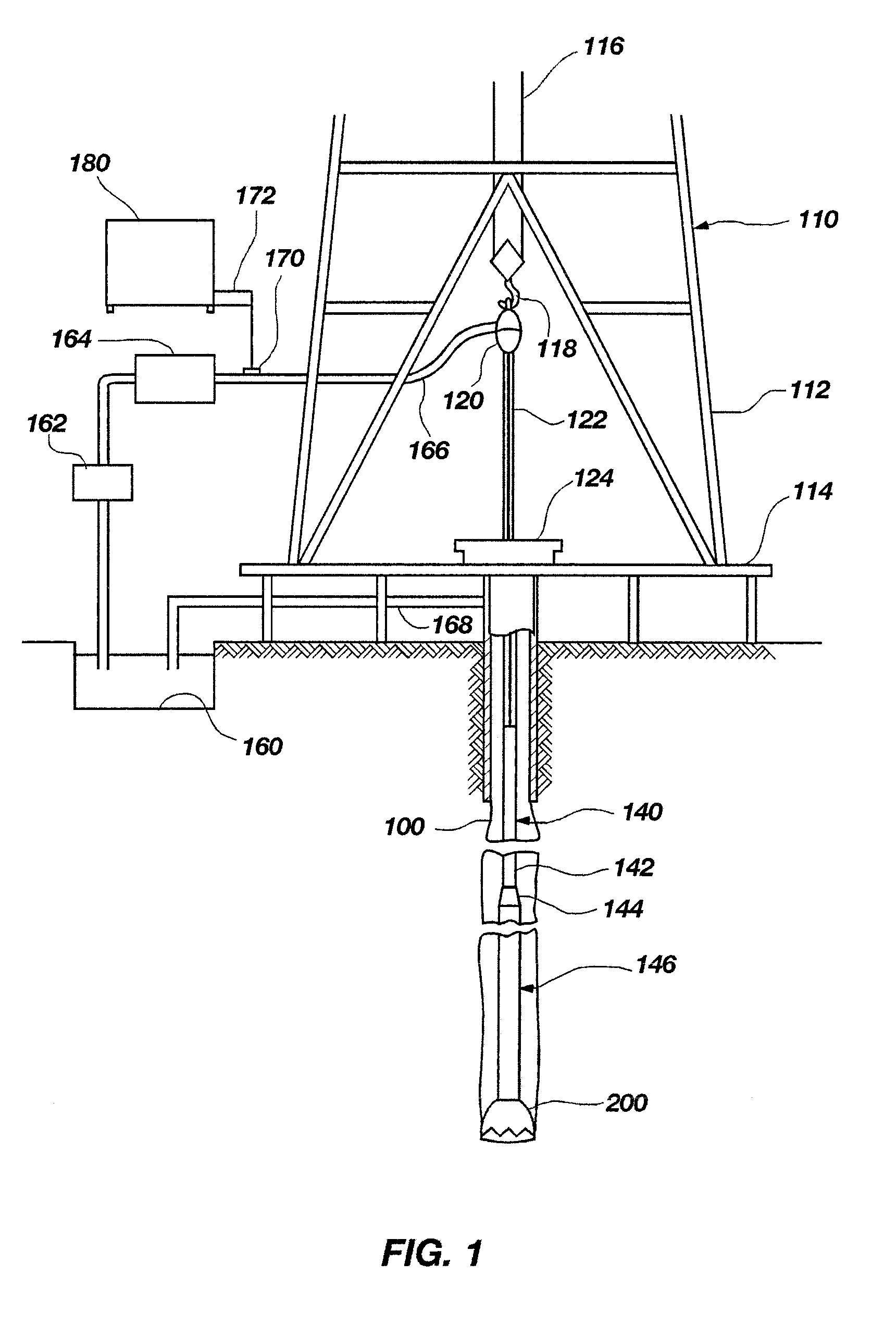
[0040]FIG. 1 depicts an example of conventional apparatus for performing subterranean drilling operations. Drilling rig 110 includes a derrick 112, a derrick floor 114, a draw works 116, a hook 118, a swivel 120, a Kelly joint 122, and a rotary table 124. A drillstring 140, which includes a drill pipe section 142 and a drill collar section 144, extends downward from the drilling rig 110 into a borehole 100. The drill pipe section 142 may include a number of tubular drill pipe members or strands connected together and the drill collar section 144 may likewise include a plurality of drill collars. In addition, the drillstring 140 may include a measurement-while-drilling (MWD) logging subassembly and cooperating mud pulse telemetry data transmission ...


PUM


Abstract

Drill bits and methods for sampling sensor data associated with the state of a drill bit are disclosed. A drill bit for drilling a subterranean formation comprises a bit body and a shank. The shank further includes a central bore formed through an inside diameter of the shank and configured for receiving a data analysis module. The data analysis module comprises a plurality of sensors, a memory, and a processor. The processor is configured for executing computer instructions to collect the sensor data by sampling the plurality of sensors, analyze the sensor data to develop a severity index, compare the sensor data to at least one adaptive threshold, and modify a data sampling mode responsive to the comparison. A method comprises collecting sensor data by sampling a plurality of physical parameters associated with a drill bit state while in various sampling modes and transitioning between those sampling modes.

Description

RELATED APPLICATIONS[0001]This application is a continuation-in-part of U.S. patent application Ser. No. 11 / 146,934 entitled METHOD AND APPARATUS FOR COLLECTING DRILL BIT PERFORMANCE DATA filed Jun. 7, 2005 now U.S. Pat. No. 7,604,072, issued Oct. 20, 2009, the disclosure of which is hereby incorporated by reference.FIELD OF THE INVENTION[0002]The present invention relates generally to drill bits for drilling subterranean formations and more particularly to methods and apparatuses for monitoring operating parameters of drill bits during drilling operations.BACKGROUND OF THE INVENTION[0003]The oil and gas industry expends sizable sums to design cutting tools, such as downhole drill bits including roller cone rock bits and fixed cutter bits, which have relatively long service lives, with relatively infrequent failure. In particular, considerable sums are expended to design and manufacture roller cone rock bits and fixed cutter bits in a manner that minimizes the opportunity for catast...

Claims


Application Information

Patent Timeline
Patent Type & Authority Patents(United States)
IPC IPC(8): E21B44/00E21B47/12E21B47/00E21B47/01
CPCE21B21/08E21B47/00E21B47/011E21B47/017E21B47/013
Inventor PASTUSEK, PAUL E.SULLIVAN, ERIC C.PRITCHARD, DARYL L.GLASGOW, KEITHTRINH, TU TIENLUTES, PAUL J.
Owner BAKER HUGHES INC
Learn More