Monitoring a conductive fluid conduit

a technology of conductive fluid conduit and monitoring system, which is applied in the direction of resistance/reactance/impedence, measurement devices, instruments, etc., can solve the problems of limited sensitivity of prior art corrosion detector arrangements, limited accuracy and sensitivity of monitoring systems, and temperature measurements that cannot additionally compensate for hydrostatic and thermal

Active Publication Date: 2014-12-04
TELEDYNE INSTR INC
View PDF3 Cites 19 Cited by
  • Summary
  • Abstract
  • Description
  • Claims
  • Application Information

AI Technical Summary

Benefits of technology

[0016]Thus, the present apparatus is able to monitor oil or gas pipe wall thickness non-intrusively over an extended area. Furthermore, the present apparatus is able to compensate for temperature variations without the need for a separate reference measurement device. In contrast, the present inv

Problems solved by technology

The sensitivity of such prior art corrosion detector arrangements is limited by various factors.
In electrical resistance corrosion monitoring systems configured with an element having an exposed surface to the environment and a reference system external to the environment such as the pipeline fluid environment, changes in fluid temperatures significantly limit the accuracy and sensitivity of the monitoring

Method used


Image

  • Monitoring a conductive fluid conduit
  • Monitoring a conductive fluid conduit
  • Monitoring a conductive fluid conduit

Examples


Embodiment Construction

[0041]In many ways, the present invention may be considered to be an extension of the corrosion sensor described in U.S. Pat. No. 6,946,855 (Cormon Limited). Therefore, the apparatus of U.S. Pat. No. 6,946,855 will first be described in detail below followed by a description of the modifications which give rise to the present invention.

The Corrosion Sensor of U.S. Pat. No. 6,946,855 (Cormon Limited)

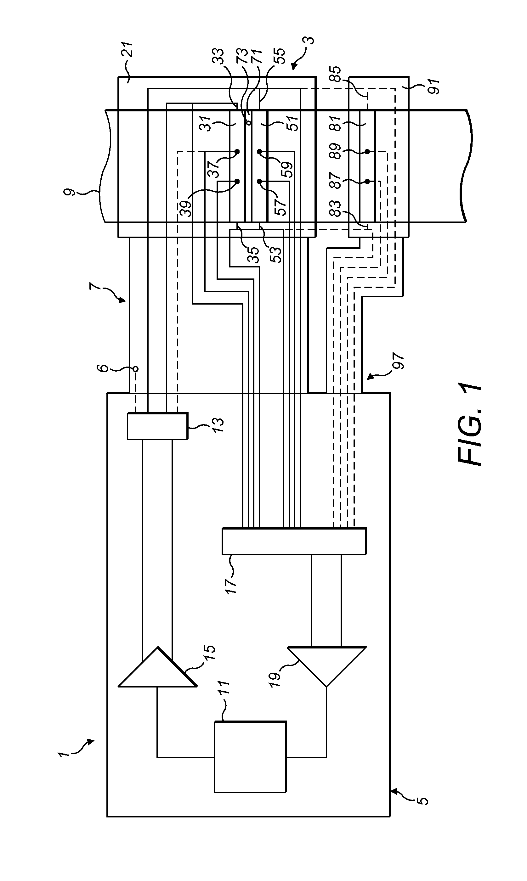
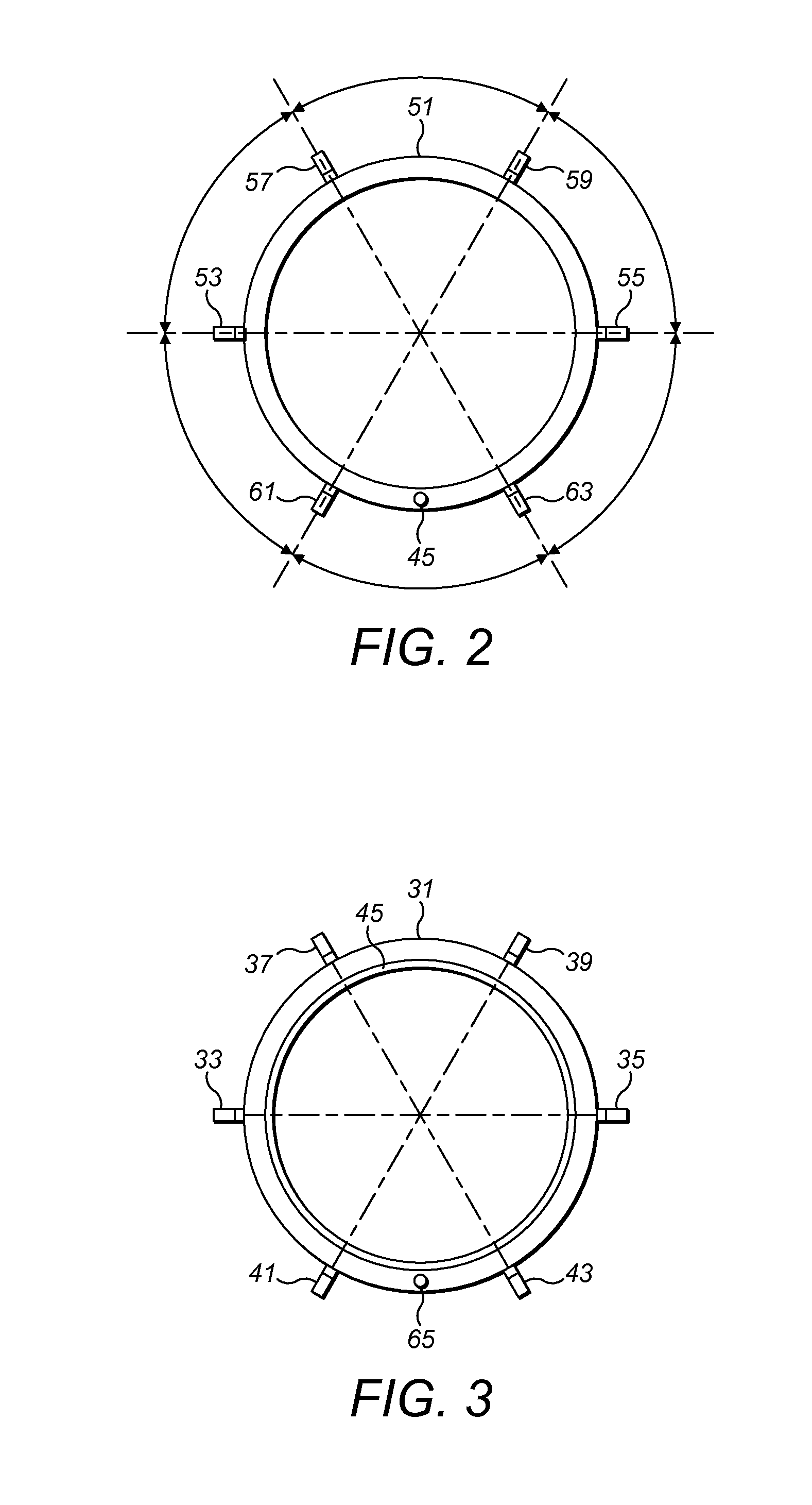
[0042]A corrosion sensor 3, which is used in a corrosion monitoring system 1 for monitoring corrosion in an environment such as a pipeline 9, is shown in FIG. 1. The corrosion monitoring system 1 generally comprises a sensor assembly 3 comprising a housing 21 for a reference element 31 and an exposed element 51, electronic circuitry 5 and a cable 7 for connecting the electronic circuitry to the sensor assembly 3.

[0043]The exposed element and the reference element are electrically connected in series and connected to a current generator 11,15 which drives current through the series circuit...


PUM


Abstract

There is described an apparatus for monitoring a conductive fluid conduit arranged to carry a fluid stream. The apparatus comprises a power supply, a plurality of electrical contact points connected to the fluid conduit, a voltage measurement device, and a processor. The power supply has a reference mode of operation and a sample mode of operation. In the reference mode of operation the power supply is operable to supply an alternating electric current through the fluid conduit at a high frequency such that the current is confined near the surface of the fluid conduit due to the skin effect. In the sample mode of operation the power supply is operable to supply an electric current through a full thickness of the fluid conduit. The voltage measurement device is operable to measure the voltage between pairs of said electrical contact points so as to obtain reference values of electrical resistance of the fluid conduit when the power supply is in the reference mode of operation and so as to obtain sample values of electrical resistance of the fluid conduit when the power supply is in the sample mode of operation. The processor is operable to modify the sample values of electrical resistance based on the corresponding reference values of electrical resistance so as to compensate for temperature variations.
There is also described a corresponding method for monitoring a conductive fluid conduit arranged to carry a fluid stream.

Description

FIELD OF THE INVENTION[0001]The present invention relates to an apparatus and method for monitoring a conductive fluid conduit. For example, the present apparatus and method may be used for monitoring oil and gas pipelines.BACKGROUND OF THE INVENTION[0002]Corrosion sensors are used in the detection and monitoring of loss of material, such as the internal surface of a pipeline wall, due to corrosion and / or erosion from interaction between the material and the environment in contact with the material. Such conditions exist in oil or gas pipelines.[0003]Commonly, corrosion sensors use electrical resistance methods to detect loss of material due to corrosion / erosion. Such sensors are described, for example, in U.S. Pat. No. 6,946,855, U.S. Pat. No. 6,680,619, U.S. Pat. No. 6,680,619, US2011 / 001498, WO01 / 70003, WO02 / 39102, WO2005 / 036152 and WO8303675.[0004]In U.S. Pat. No. 6,946,855 (Cormon Limited), an apparatus is disclosed for monitoring the effect on a material of exposure to a fluid...

Claims


Application Information

Patent Timeline
IPC IPC(8): G01N17/04G01N27/20
CPCG01N27/20G01N17/04
Inventor CLARKE, DANIELHEMBLADE, BARRY JOHN
Owner TELEDYNE INSTR INC
Why Eureka
Try Eureka