Optical connector with optical fiber

a technology of optical fibers and optical connectors, applied in the field of optical connectors with optical fibers, can solve the problems of complex grinding process, difficult process control, and inability to achieve the effect of improving the quality of optical fibers

Inactive Publication Date: 2010-12-14
FUJIKURA LTD
View PDF26 Cites 59 Cited by
  • Summary
  • Abstract
  • Description
  • Claims
  • Application Information

AI Technical Summary

Problems solved by technology

However, it is known that the convex grinding process is complicated, and the process control is difficult, so grinding deficiencies, such as an insufficiency of the protruding amount (protruding length) of the optical fibers, dispersion in the protruding amount, angular deficiency of the ferrule end face, and the like, are likely to occur.
In particular in a super multi-fiber optical connector, in which multiple rows of optical fiber openings are arranged in two directions, the area of the connecting end face is large compared with the case where the optical fiber openings are arranged in one row, and hence there is a problem in that grinding defects are likely to occur.
Therefore, in the case where the dispersion in the protruding amount is large, it is difficult to compensate (equalize) completely.
However, it is proven that if the Young's modulus of the resin coating layer is reduced in order to compensate for great dispersion, conversely the optical connection characteristics deteriorate.
That is, it is proven that if the Young's modulus of the resin coating layer is too high, the resin coating layer loses flexibility, so that its buffering function deteriorates, but conversely, if the Young's modulus of the resin coating layer is too low, the core locations of the ends of the optical fibers are unstable, so that the optical connection characteristics deteriorate.
In this manner, in a ferrule with a standard shape, the width and thickness of the connecting end face are limited, and there is a limitation to the increase in the number of optical fiber openings.
Therefore, it is not possible to significantly increase the number of optical fibers to be connected.
Furthermore, since the internal cavity (adhesive filled cavity) is small, if a large number of optical fibers are inserted forcibly, the optical fibers will be damaged, or optical loss will occur.
Therefore, there is a limitation to the number of optical fibers to be connected.
On the other hand, for the optical connector housings for housing ferrules, since internationally there are de facto standards and de jure standards (for example, MPO connector: conformed to JIS C5980), it is difficult to increase the size of the ferrule.
Moreover, in the case where the size of the ferrule is increased, in an application in which a plurality of ferrules is mounted on an optical wiring substrate at a high density, there is a problem in that the packing density of the ferrules drops.
Owing to the above reasons, it is not easy to increase the number of optical fibers to be connected to the ferrule.

Method used


Image

  • Optical connector with optical fiber
  • Optical connector with optical fiber
  • Optical connector with optical fiber

Examples


Embodiment Construction

[0050]Hereunder is a description of the best mode for carrying out the present invention, with reference to the drawings.

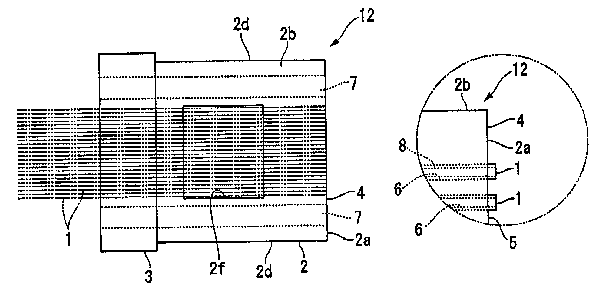
[0051]As shown schematically in FIG. 6A and FIG. 6B, a multi-fiber optical connector 20 (sometimes referred to hereunder simply as an optical connector) is assembled at the end of an optical fiber 16, and has a ferrule 12, a housing 11 for housing the ferrule 12, a coupling 13 provided on the outside of the housing 11, a spring 15 housed inside of the housing 11, and a boot 17 provided at the rear of the housing 11.

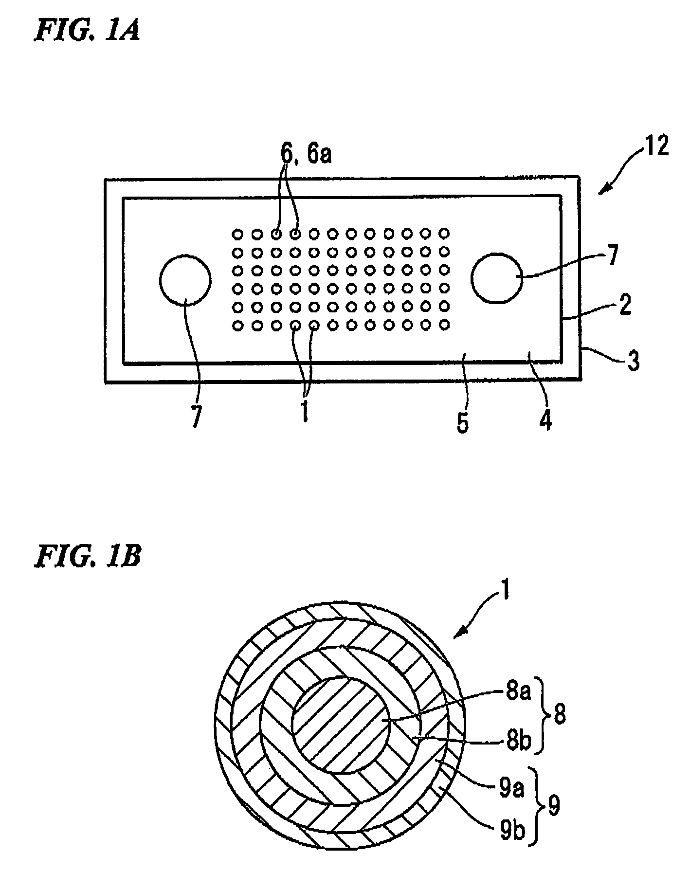
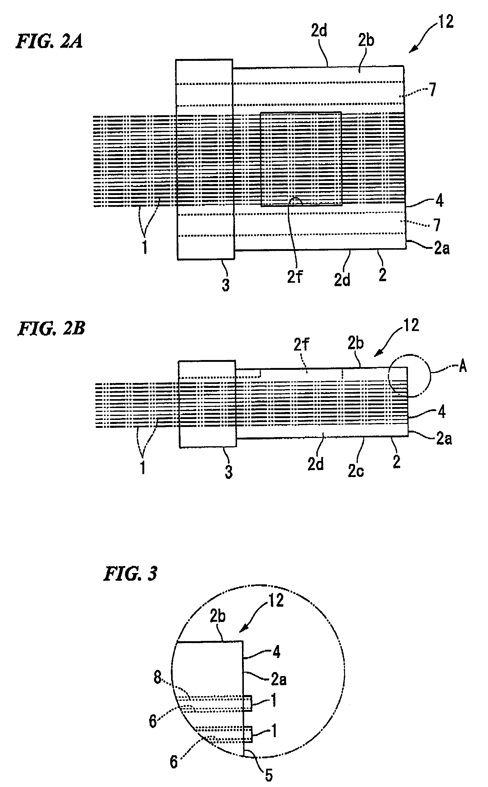
[0052]In the following description, the direction toward the left (connection direction) of FIG. 6A is sometimes designated the front while its opposite direction is sometimes designated the rear. Furthermore, the direction (vertical direction of FIG. 1A) corresponding to the short side of the connecting end face 4 of the ferrule 12 is designated the thickness direction, while the direction (horizontal direction of FIG. 1A) corresponding to the long sid...


PUM

PropertyMeasurementUnit
outer diameteraaaaaaaaaa
Young's modulusaaaaaaaaaa

Abstract

In an optical connector with optical fibers in which silica glass optical fibers with resin coating layers remaining attached are connected in optical fiber openings of a ferrule made from resin, at least a part of the resin coating layer of the optical fiber is glued to an inner face of the optical fiber opening, an outer diameter of the resin coating layer of the optical fiber is less than or equal to 125 μm, and the Young's modulus of the resin coating layer is less than the Young's modulus of the ferrule, and the Young's modulus of the resin coating layer is 1500 to 10000 MPa.

Description

[0001]The present invention claims priority on Japanese Patent Application No. 2008-42440, filed on Feb. 25, 2008, and Japanese Patent Application No. 2008-319338, filed on Dec. 16, 2008, and the contents of which are incorporated herein by reference.BACKGROUND OF THE INVENTION[0002]1. Field of the Invention[0003]The present invention relates to an optical connector with optical fibers, and in particular it relates to an optical connector with optical fibers in which small diameter optical fibers are connected.[0004]2. Description of Related Art[0005]Single fiber optical connectors and multi-fiber optical connectors are used in optical interconnection techniques. As a multi-fiber optical connector, an MPO type optical connector is widely used (for example, refer to Japanese Unexamined Utility Model Application, First Publication No. S62-104203).[0006]An optical fiber to be inserted in the optical fiber opening of a ferrule of an optical connector is a bare optical fiber in which a r...

Claims


Application Information

Patent Timeline
Patent Type & Authority Patents(United States)
IPC IPC(8): G02B6/36
CPCG02B6/3885G02B6/3644G02B6/3652G02B6/3664G02B6/368G02B6/3696G02B6/3821
Inventor NISHIMURA, AKITOISHIKAWA, TAKAAKIFUJIWARA, KUNIHIKOHAYASHI, YUKIO
Owner FUJIKURA LTD
Why Eureka
Try Eureka