Contoured reamer teeth

a technology of reamer teeth and reamer shells, which is applied in the field of surgical products, can solve the problems of increasing the difficulty of designing medical instruments and implants, reducing mechanical strength, and increasing the difficulty of designers, so as to reduce the number of teeth, reduce the size of a typical chip, and reduce the cutting pressure on each tooth

Active Publication Date: 2010-12-14
VIANT AS&O HLDG LLC
View PDF13 Cites 10 Cited by
  • Summary
  • Abstract
  • Description
  • Claims
  • Application Information

AI Technical Summary

Benefits of technology

[0011]The above problems are solved through the provision of an acetabular reamer for cutting a required cut shape, the reamer having a cutting shell on which are located a series of doubly-curved cutting teeth thereon of a quantity sufficient to substantially reduce a cutting pressure on each tooth as well as to reduce a size of a typical chip generated upon cutting. Substantially all the teeth each have a matched arc cutting edge of substantial length that has a cutting profile which substantially matches a profile of a shape to be cut. Such a configuration reduces the number of teeth required to cut the shape. Further, by punching up or forming a larger number of smaller teeth, it is easier to maintain the spherical shape of the reamer.
[0012]The invention thus gives an improved quality of cut surface and allows fewer teeth to be employed.

Problems solved by technology

Meeting this additional requirement provides an additional challenge to the designers of medical instruments and implants.
However, when this is done, mechanical strength decreases.
Further, it is more difficult in this case to insure that the cut profile of each tooth overlaps.
Larger teeth have been attempted but either the chip size and cutting stresses were too large or the reamer was too complex.
Further, due to the large opening adjacent the larger teeth, mechanical strength was sacrificed.
Such a tooth form thus is not supported in that no structure is provided to help maintain the form of the tooth (other than the tooth itself) when faced with the sometimes unusually high cutting pressures of reaming.
Further, the integrity of the spherical form of the reamer can be affected when there are a limited number of extensive slits of cuts in the spherical.
This integrity is affected by the fact that high stresses are induced at the sharp corners of the slits.

Method used


Image

  • Contoured reamer teeth
  • Contoured reamer teeth
  • Contoured reamer teeth

Examples


Embodiment Construction

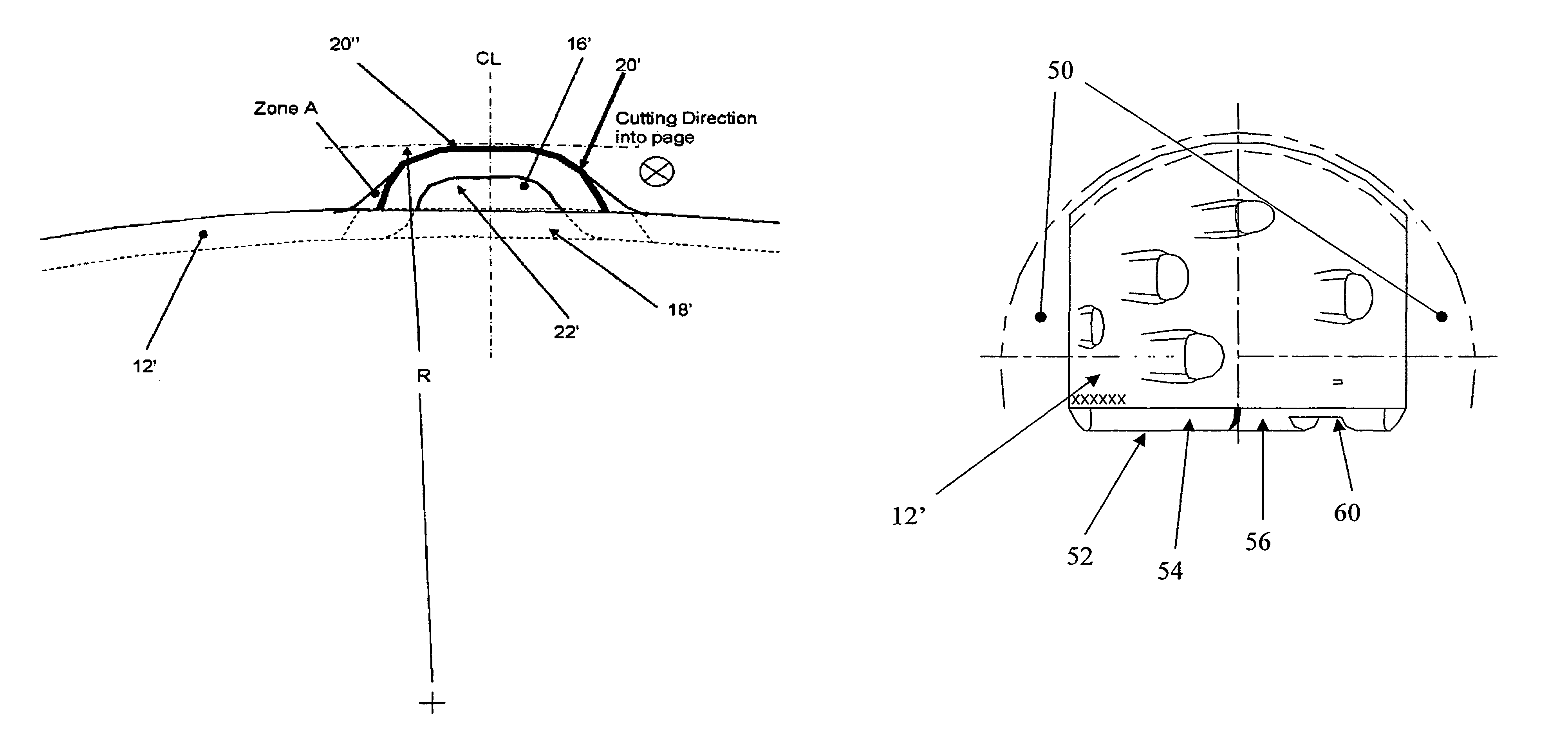
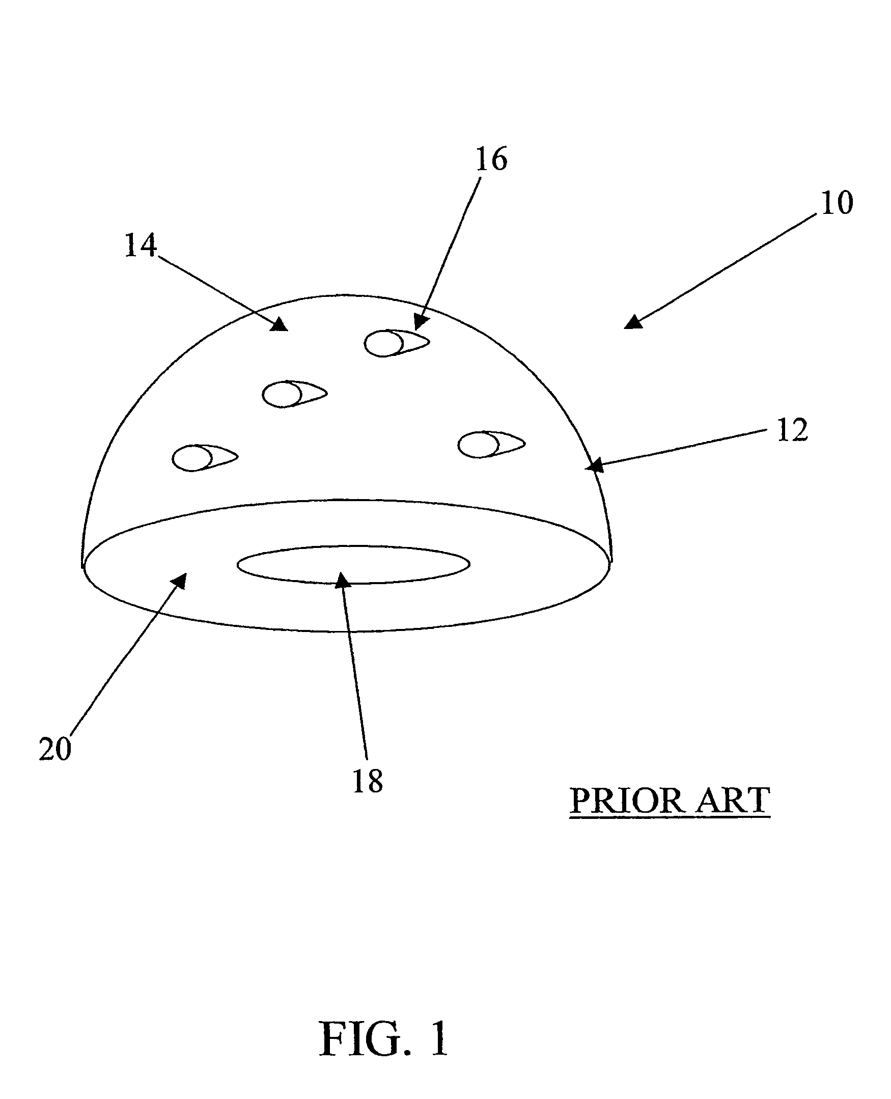
[0022]Referring to FIG. 1, a typical acetabular reamer 10 of the prior art is shown. The reamer 10 has a cutting bowl or shell 12 defining a surface 14 on which are located teeth 16 adjacent openings 18. A base 20 provides a tool-engaging device (not shown) which typically engages an opening 21 therein.

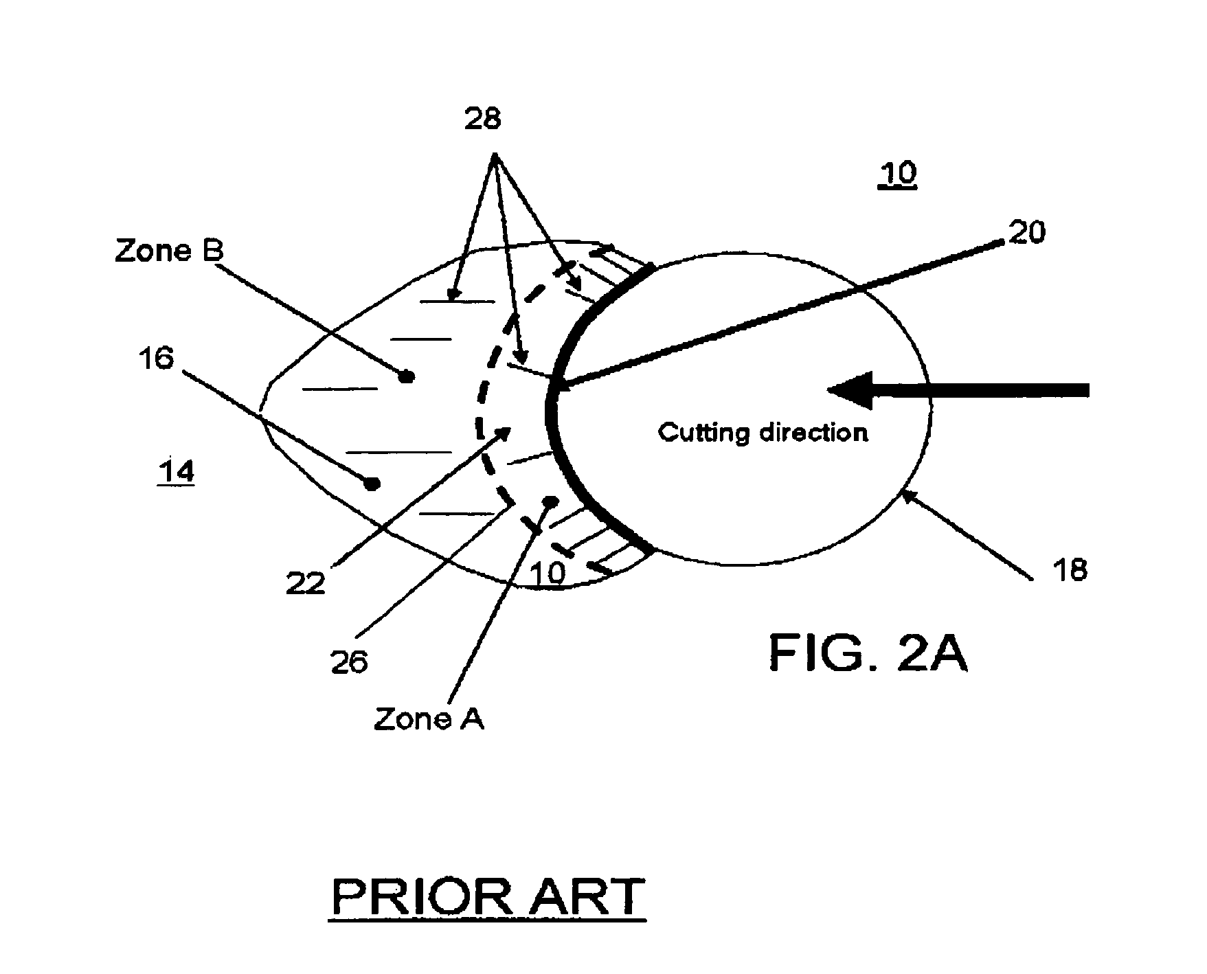
[0023]Referring now to FIG. 2A, a tooth 16 of the reamer 10 is shown. The tooth 16 has a diverging surface 22 (“rise”, marked Zone A) backing up the cutting edge 20. Some distance behind the cutting edge 20 (to the left of the cutting edge in the figure), about where the dashed line 26 is located, this surface begins to curve inwardly toward the surface of Zone B, and then towards the reamer cutting bowl surface 14. Surface reflection lines 28 help indicate the form of these surfaces.

[0024]Referring now to FIG. 2B, a cross sectional side view of the tooth profile 32 of the prior art reamer 10 is shown. The form of the profile 32 of the rise 22 is non-linear as indicated (compare profi...


PUM


Abstract

An acetabular reamer (10′) for cutting a required cut shape. The reamer has a cutting shell (12′) having a series of doubly curved cutting teeth (16′) thereon of a quantity to substantially reduce a cutting pressure on each tooth as well as to reduce a size of a typical chip generated upon cutting. Substantially all the teeth each have a matched arc cutting edge (20′) of substantial length that has a cutting profile which substantially matches a profile of a shape to be cut. Such a configuration reduces the number of teeth required to cut the shape.

Description

CROSS REFERENCE TO RELATED APPLICATIONS[0001]This application is a §371 application of PCT application no. PCT / IB2003 / 0000092, filed Jan. 16, 2003, and claims priority to U.S. provisional application Ser. No. 60 / 349,103, of the same title, filed Jan. 16, 2002.BACKGROUND OF THE INVENTION[0002]The invention relates to surgical products, and in particular, to surgical reamers for cutting shaped cavities in bone.[0003]In order to produce a shaped cavity in bone for a hip implant, which requires smooth walls and accurate shape, it is advantageous that the reamer shell or cutting bowl be hemispherical. Further, the cutting teeth must be properly located and oriented. Still further, the tooth height is important to the size of bone chip and thus to the accuracy of the shape cut by the reamer.[0004]In most cases, an implant in a hip socket is best fixed to a concave, hemispherical cavity. However, such a shape is not strictly necessary. Other acetabular cutting shells are non-hemispherical ...

Claims


Application Information

Patent Timeline
Patent Type & Authority Patents(United States)
IPC IPC(8): A61B17/00A61B17/16
CPCA61B17/1666A61B17/16
Inventor LECHOT, ANDRE
Owner VIANT AS&O HLDG LLC
Why Eureka
Try Eureka