

Electrostatic induction generator
a technology of induction generator and electric motor, which is applied in the direction of generator/motor, machine/engine, transportation and packaging, etc., can solve the problems of not being disadvantageously able to withstand the reflow soldering temperature of about 250° c. required, low heat resistance of the resin material,
- Summary
- Abstract
- Description
- Claims
- Application Information
AI Technical Summary
Problems solved by technology
Method used
Image

Examples
first embodiment
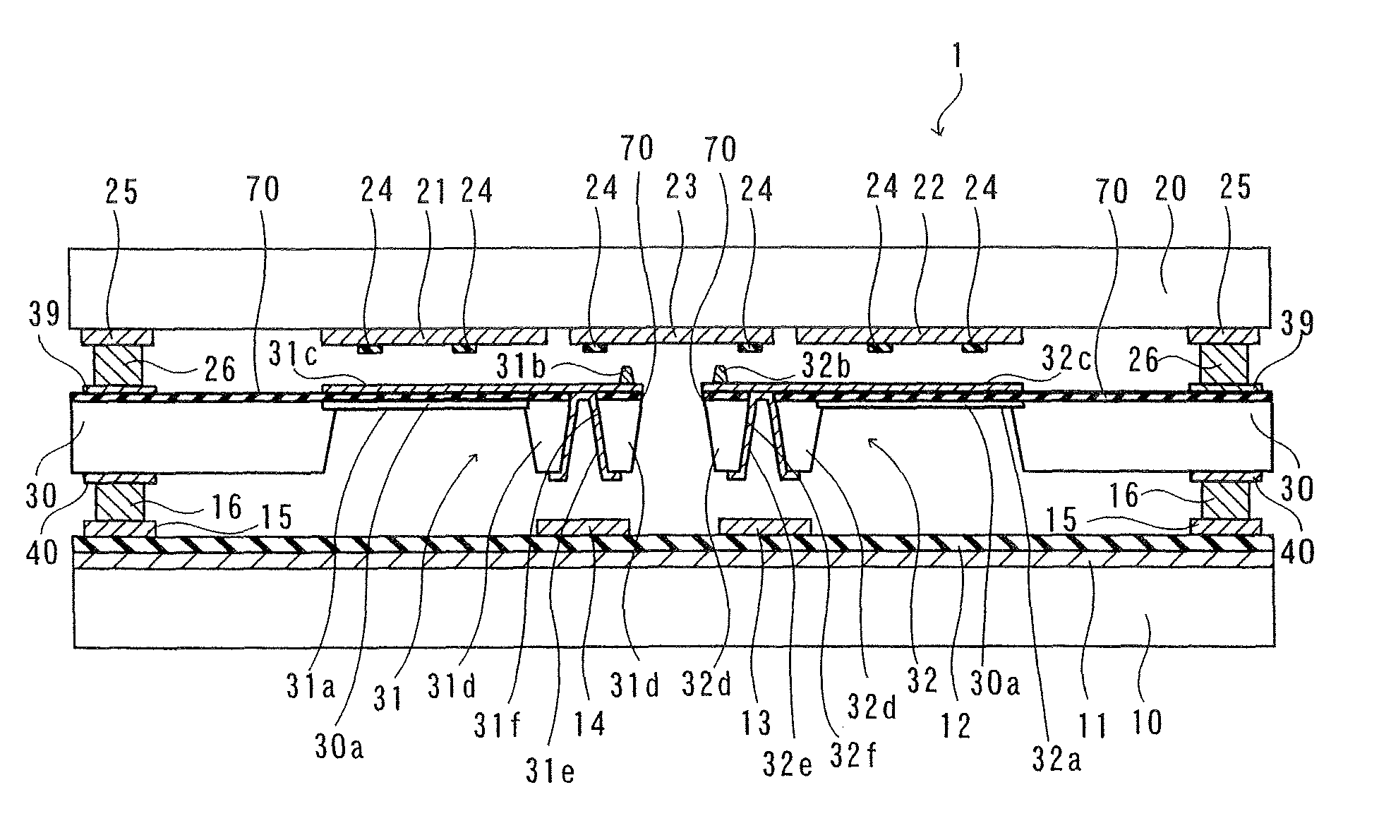
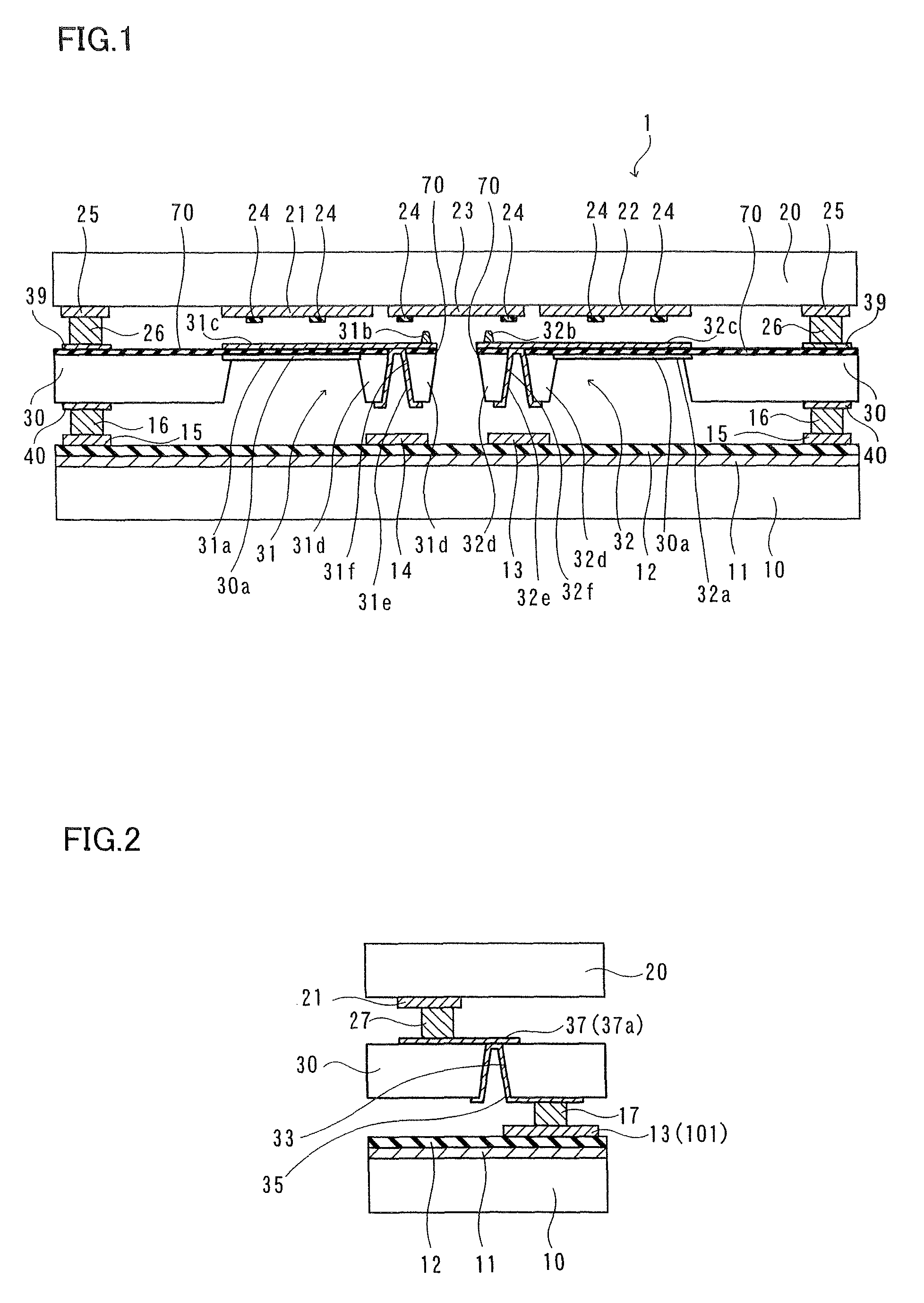
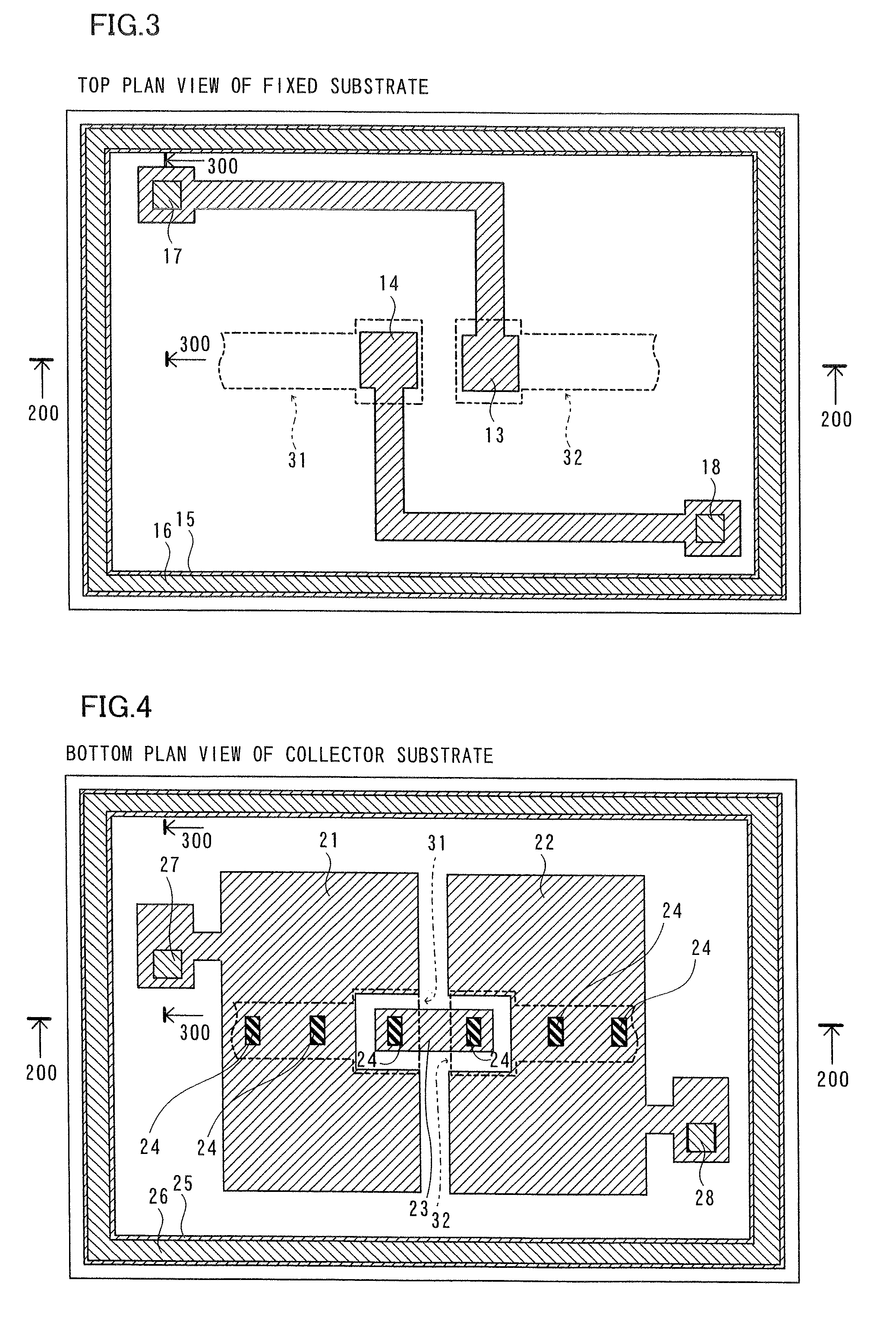
[0026]A structure of an electrostatic induction generator 1 according to a first embodiment will be described with reference to FIGS. 1 to 6.
[0027]The electrostatic induction generator 1 according to the first embodiment is constituted by three layers of a fixed substrate 10 made of glass, a collector substrate 20 made of glass, a vibrating substrate 30 consisting of silicon arranged between the fixed substrate 10 and the collector substrate 20, as shown in FIG. 1. The fixed substrate 10 and the collector substrate 20 are examples of the “first substrate” and the “third substrate” in the present invention respectively. The vibrating substrate 30 is an example of the “second substrate” in the present invention. The structure of the electrostatic induction generator 1 will be now described in detail.
[0028]As shown in FIG. 1, a floating electrode 11 of Au (upper layer) / Cr (lower layer) having a thickness of about 2 μm is formed on an upper surface of the fixed substrate 10 having a thi...
second embodiment
[0059]With reference to FIGS. 27 to 30, an electrostatic induction generator 1b according to a second embodiment is formed with first and second collector electrodes 101 and 102 also on a fixed substrate 10 dissimilarly to the electrostatic induction generator according to the aforementioned first embodiment.
[0060]The electrostatic induction generator 1b according to the second embodiment is constituted by three layers of a fixed substrate 10, a collector substrate 20, a vibrating substrate 110 consisting of silicon arranged between the fixed substrate 10 and the collector substrate 20, as shown in FIG. 27. The vibrating substrate 110 is an example of the “second substrate” in the present invention. The structure of the electrostatic induction generator 1b will be now described in detail.
[0061]As shown in FIG. 27, the floating electrode 11 is formed on an upper surface of the fixed substrate 10. A insulating film 12 is formed on an upper surface of the floating electrode 11. Accordi...
third embodiment
[0074]With reference to FIGS. 31 and 32, a first vibrating electrode portion 133 and a second vibrating electrode portion 134 vibrate in directions along surfaces of a first collector electrode 122 and a second collector electrode 123 respectively in an electrostatic induction generator 1c according to a third embodiment, dissimilarly to the electrostatic induction generator 1 according to the aforementioned first embodiment.
[0075]The electrostatic induction generator 1c according to the third embodiment is constituted by three layers of a fixed substrate 10, a collector substrate 20, a vibrating substrate 130 consisting of silicon arranged between the fixed substrate 10 and the collector substrate 20, as shown in FIG. 31. The vibrating substrate 130 is an example of the “second substrate” in the present invention. The structure of the electrostatic induction generator 1c will be now described in detail.
[0076]As shown in FIG. 31, a floating electrode 11 is formed on an upper surface...
PUM
 Abstract
Description
Claims
Application Information