Acoustic transducer and microphone
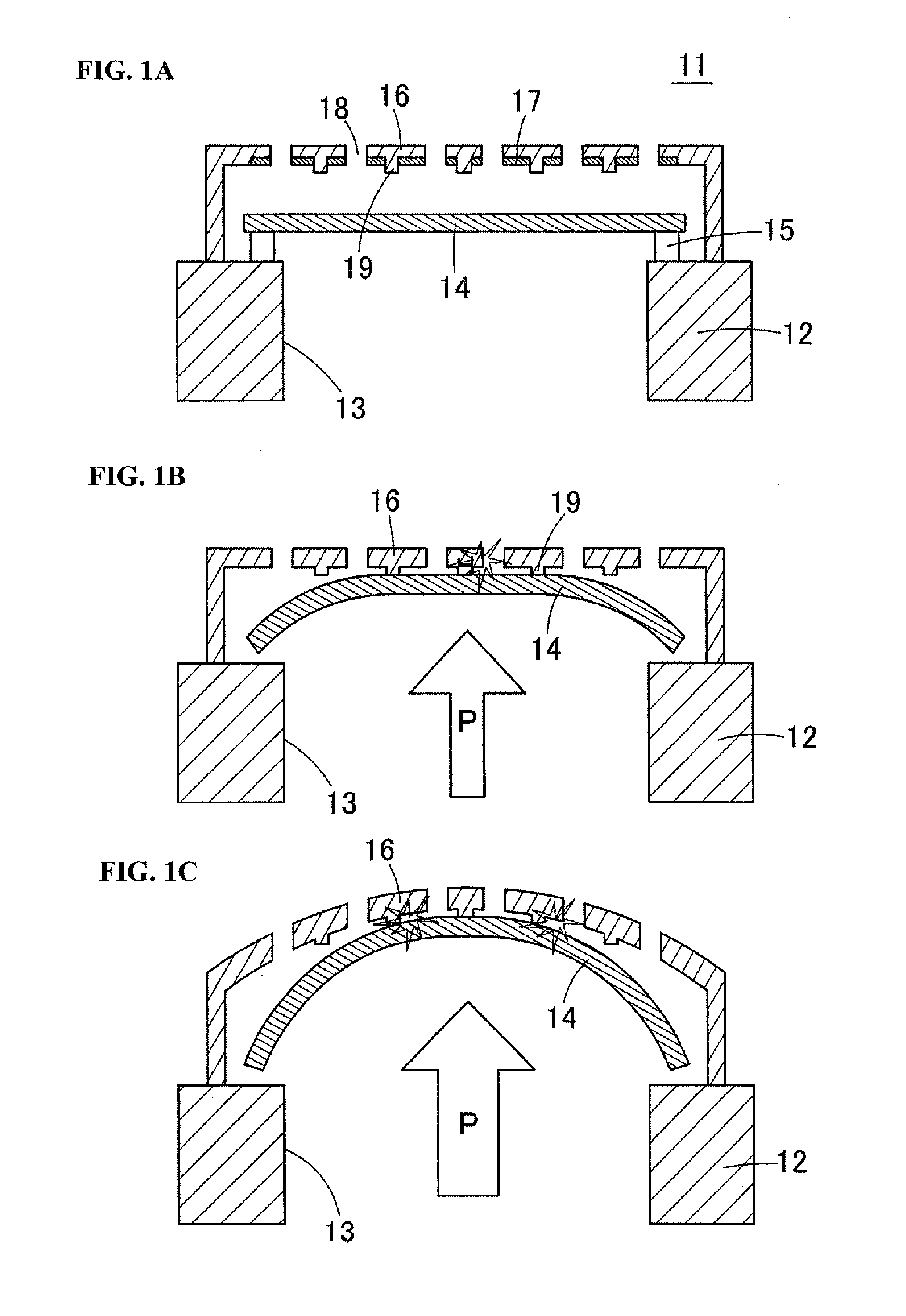
a technology of acoustic transducers and microphones, applied in the direction of electrical transducers, transducer types, and semiconductor electrostatic transducers, can solve the problems of poor damage resistance of acoustic sensors, lack of design flexibility, and risk of diaphragms and back plates becoming damaged or cracked, etc., to suppress the deformation of the vibrating electrode plate (diaphragm) and avoid the concentration of stress and damage
- Summary
- Abstract
- Description
- Claims
- Application Information
AI Technical Summary
Benefits of technology
Problems solved by technology
Method used
Image
Examples
embodiment 1
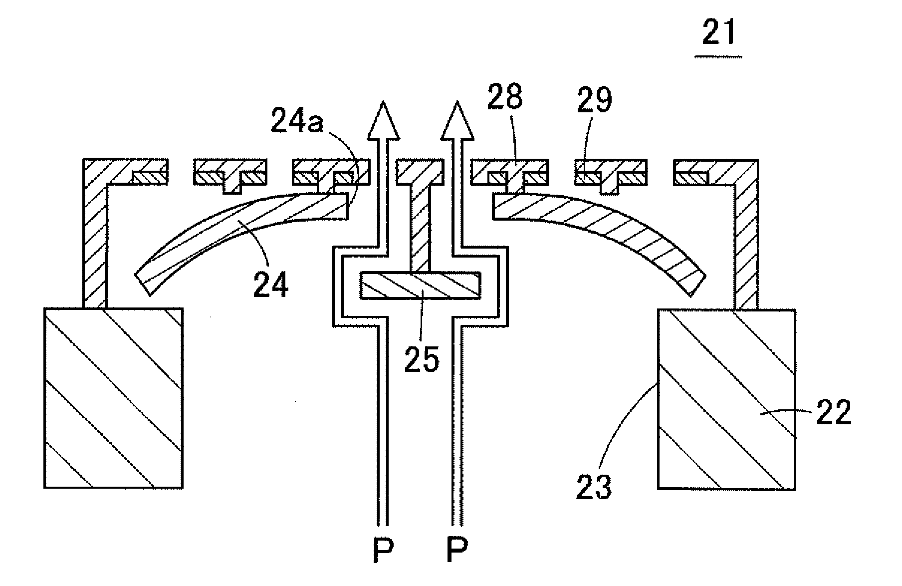
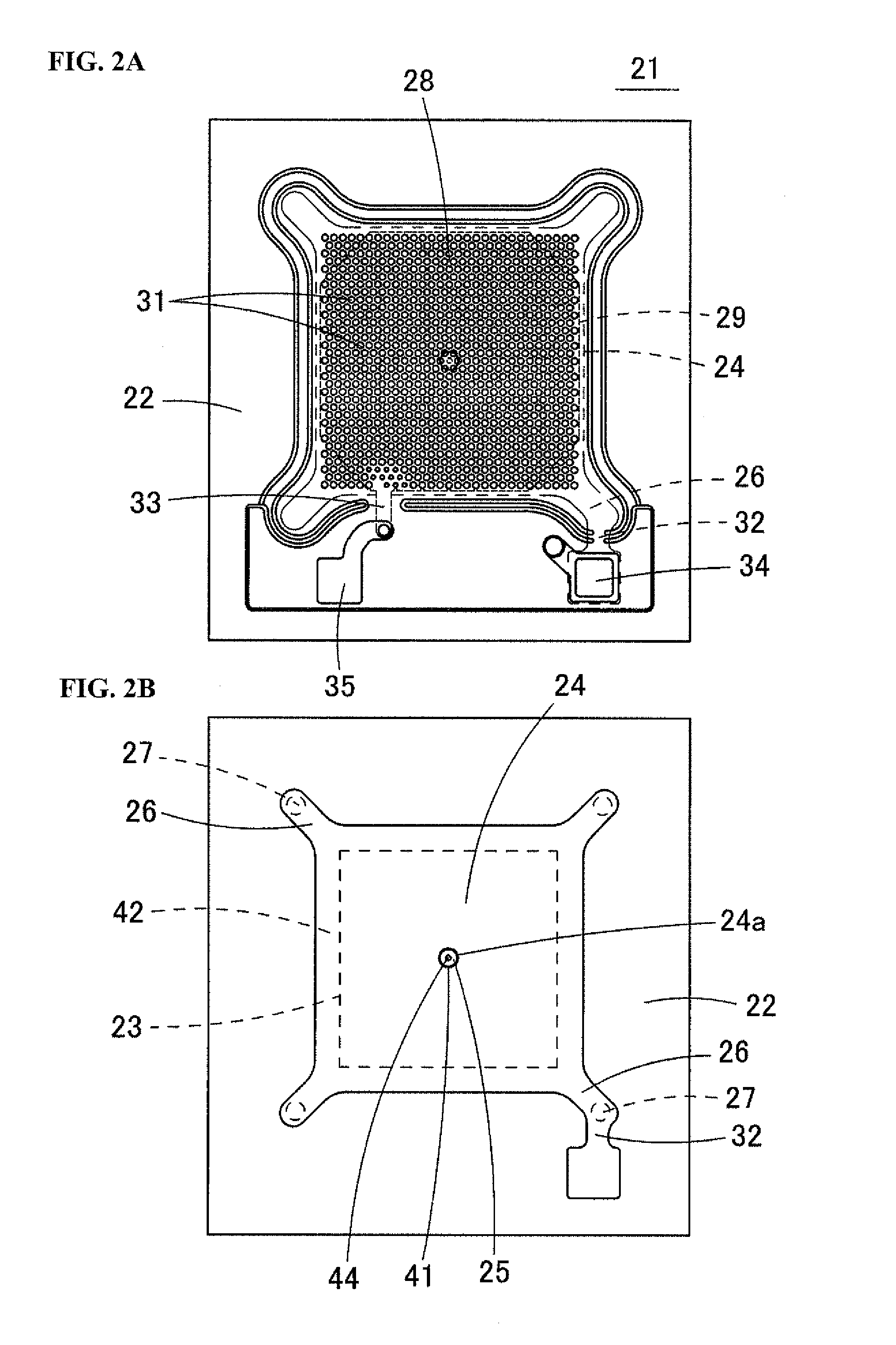
[0055]The following describes an acoustic transducer according to Embodiment 1 of the present invention, that is to say an acoustic sensor 21, with reference to the drawings. FIG. 2A is a plan view of the acoustic sensor 21 according to Embodiment 1 of the present invention. FIG. 2B is a plan view of a state in which a diaphragm 24 is exposed by removing a back plate 28 and a fixed electrode plate 29 from the acoustic sensor 21 shown in FIG. 2A. FIG. 3 is a cross-sectional diagram of the acoustic sensor 21.
[0056]The acoustic sensor 21 is a capacitance type of device created using MEMS technology. As shown in FIG. 3, in the acoustic sensor 21, the diaphragm 24 (vibrating electrode plate) is provided on a substrate 22, which is made of a silicon substrate or the like, via anchors 27, and the fixed electrode plate 29 is provided above the diaphragm 24 in opposition to the diaphragm 24.
[0057]A rectangular cavity 23 is formed in the substrate 22 so as to pass from the upper surface to th...
embodiment 2
[0082]FIG. 7A is a schematic cross-sectional diagram showing an acoustic sensor 51 according to Embodiment 2 of the present invention. FIG. 7B is a plan view showing an enlargement of the central portion of a back plate 28 of the acoustic sensor 51.
[0083]In the acoustic sensor 51, multiple support portions 44 extend downward from the central portion of the lower surface of the back plate 28, and the regulation portion 25 is supported by these support portions 44. If the regulation portion 25 is supported by multiple support portions 44, the rigidity of the regulation portion 25 increases, and the regulation portion 25 is not likely to undergo deformation even when subjected to a large degree of pressure, thus making it possible to prevent a reduction in the distance between the edge of regulation portion 25 and the edge of the opening 24a of the deformed diaphragm 24.
[0084]Remarks Regarding Variations
[0085]Although the opening 24a and the regulation portion 25 are circular in one or...
embodiment 3
[0088]FIG. 10 is a cross-sectional diagram showing an acoustic sensor 61 according to Embodiment 3 of the present invention, a feature of which is that the diaphragm 24 is provided above the fixed electrode plate 29. In the acoustic sensor 61, a flat plate-shaped back plate 28 is provided on the upper surface of the substrate 22 via an insulation layer 62. The fixed electrode plate 29 is formed on the upper surface of the back plate 28. Multiple acoustic holes 31 are formed in the back plate 28 and the fixed electrode plate 29 above the cavity 23. Also, the diaphragm 24 is arranged so as to oppose the fixed electrode plate 29 above the back plate 28. Leg pieces 26 extending from the diaphragm 24 are supported by anchors 27 provided on the upper surface of the back plate 28.
[0089]The opening 24a is formed in the central portion of the diaphragm 24, and the regulation portion 25 is arranged inside the opening 24a. The regulation portion 25 is fixed to the upper edge of the support por...
PUM
 Abstract
Description
Claims
Application Information
 - R&D
- Intellectual Property
- Life Sciences
- Materials
- Tech Scout
- Unparalleled Data Quality
- Higher Quality Content
- 60% Fewer Hallucinations
Browse by: Latest US Patents, China's latest patents, Technical Efficacy Thesaurus, Application Domain, Technology Topic, Popular Technical Reports.
© 2025 PatSnap. All rights reserved.Legal|Privacy policy|Modern Slavery Act Transparency Statement|Sitemap|About US| Contact US: help@patsnap.com


