Capacitance type transducer and acoustic sensor

a technology of capacitive transducer and acoustic sensor, which is applied in the direction of semiconductor electrostatic transducers, diaphragm construction, instruments, etc., can solve the problems of vibration electrode film deformation, inconvenience, deterioration of frequency characteristics, etc., to prevent vibration electrode film damage, suppress excessive deformation of vibrating electrode film, and maintain favorable frequency characteristics

Active Publication Date: 2017-10-05
MMI SEMICON CO LTD
View PDF1 Cites 7 Cited by
  • Summary
  • Abstract
  • Description
  • Claims
  • Application Information

AI Technical Summary

Benefits of technology

[0058]According to the present invention, with respect to a capacitance type transducer, damage to a vibrating electrode film can be avoided when excessive pressure is applied to the vibrating electrode film by suppressing excessive deformation of the vibrating electrode film, while maintaining favorably frequency characteristics during detection of pressure. As a result, reliability of the capacitance type transducer can be improved, while maintaining more favorably performance thereof.

Problems solved by technology

On the other hand, since a capacitance type transducer fabricated using MEMS technology is constituted by a thinned vibrating electrode film and a back plate, there is a risk that the vibrating electrode film may deform significantly and break when subjected to excessive pressure and the like.
Such inconveniences may occur when, for example, high sound pressure is applied inside the capacitance type transducer as well as when air blowing is performed in a mounting process and when the capacitance type transducer is dropped.
While such inconveniences can conceivably be addressed by providing the vibrating electrode film with a hole for releasing pressure and releasing pressure from the hole when excessive pressure is applied, such a measure may cause a deterioration in frequency characteristics as a capacitance type transducer, particularly a decline in sensitivity in a low-frequency range.
However, in the invention described above, since the plug section and a supporting member are separate members, the invention not only necessitates a more complicated manufacturing process but also entails a risk that the plug section may become detached from the supporting member and impair functionality.

Method used


Image

  • Capacitance type transducer and acoustic sensor
  • Capacitance type transducer and acoustic sensor
  • Capacitance type transducer and acoustic sensor

Examples


first embodiment

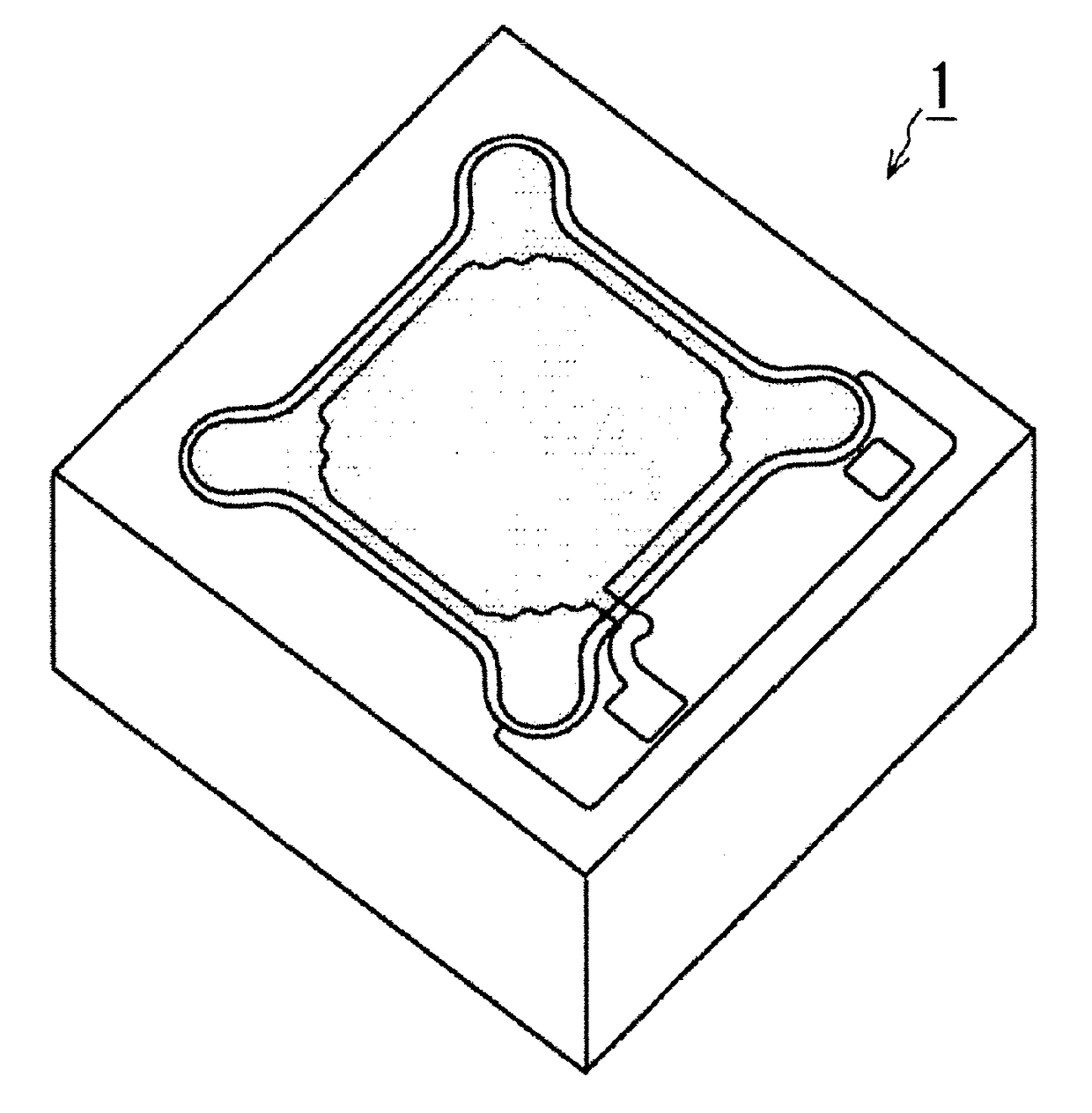
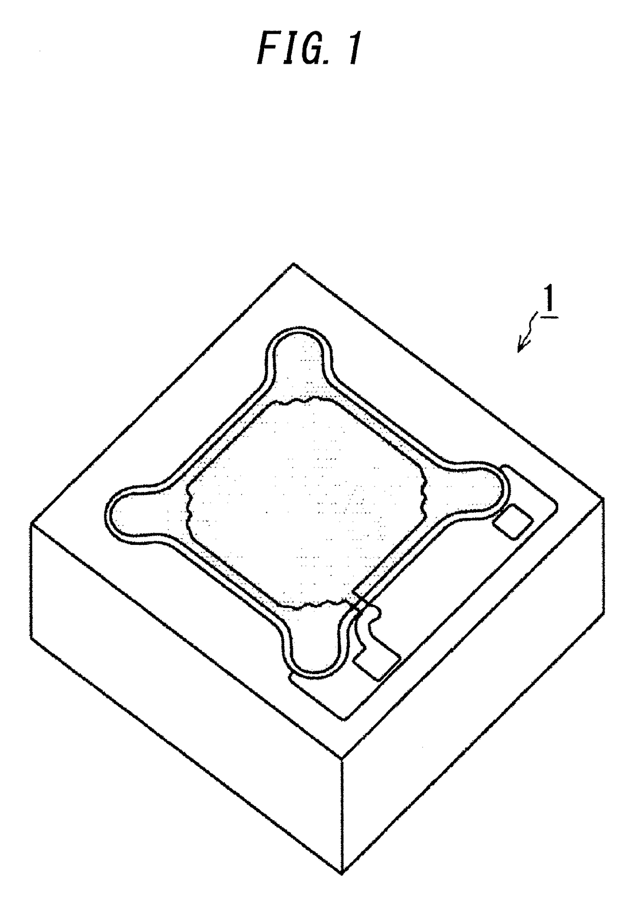
[0081]Hereinafter, embodiments of the invention of the present application will be described with reference to the drawings. The embodiments described below merely represent aspects of the invention of the present application and are not intended to limit the technical scope of the present invention. While the invention of the present application can be applied to all electrostatic transducers, a case where an electrostatic transducer is used as an acoustic sensor will be described below. However, a sound transducer according to the present invention can be used as sensors other than an acoustic sensor as long as a displacement of a vibrating electrode film can be detected. For example, in addition to a pressure sensor, a sound transducer according to the present invention may be used as an acceleration sensor, an inertial sensor, and the like. In addition, a sound transducer according to the present invention may be used as elements other than a sensor such as a speaker which conve...

second embodiment

[0117]Next, a second embodiment according to the present invention will now be described. In the first embodiment, an example has been described in which, when the protruding section 17b penetrates through the pressure release hole 15b of the vibrating electrode film 15 to close the pressure release hole 15b and excessive pressure is applied to the vibrating electrode film 15, the penetration of the pressure release hole 15b by the protruding section 17b is canceled and the entire pressure release hole 15b is exposed.

[0118]In contrast, in the second embodiment, an example will be described in which a protruding section of a back plate covers a pressure release hole of a vibrating electrode film in a state of normal use prior to the vibrating electrode film deforming significantly and the protruding section separates from the pressure release hole when excessive pressure is applied to the vibrating electrode film.

[0119]Actions of a pressure release hole 25b of a vibrating electrode f...

third embodiment

[0124]Next, a third embodiment according to the present invention will now be described. In the third embodiment, an example will be described in which a protruding section is provided on a side surface of a back plate and, when excessive pressure is applied to a vibrating electrode film, a gap between the protruding section and an end surface of the vibrating electrode film increases to release pressure.

[0125]Actions of vibrating electrode films 35, 45, 55 and protruding sections 37b, 47b, and 57b of back plates 37, 47, and 57 according to the present embodiment will be described with reference to FIGS. 12A-12C. FIG. 12A is a diagram showing actions of the vibrating electrode film 35 and the protruding section 37b of the back plate 37 according to the present embodiment when excessive pressure is applied to the vibrating electrode film 35. FIG. 12B is a diagram showing actions of the vibrating electrode film 45 and the protruding section 47b of the back plate 47 according to the pr...


PUM

PropertyMeasurementUnit
inclination angleaaaaaaaaaa
distanceaaaaaaaaaa

Abstract

A capacitance type transducer has a substrate with an opening on a surface thereof, a back plate arranged to oppose the opening of the substrate, and a vibrating electrode film arranged to oppose the back plate across a gap between the vibrating electrode film and the back plate. The capacitance type transducer converts a displacement of the vibrating electrode film into a change in capacitance between the vibrating electrode film and the back plate. The capacitance type transducer has a pressure releasing flow channel which is an air flow channel formed by a gap between a part of the vibrating electrode film and a protruding portion integrally provided on the back plate.

Description

CROSS-REFERENCE TO RELATED APPLICATIONS[0001]This application is based upon and claims the benefit of priority of Japanese Patent Application No. 2015-050100, filed on Mar. 12, 2015, and International Patent Application No. PCT / JP2016 / 057630, filed on Mar. 10, 2016, the contents of which are incorporated herein by reference in their entirety.BACKGROUNDTechnical Field[0002]The present application relates to a capacitance type transducer and to an acoustic sensor including the capacitance type transducer. More specifically, the present invention relates to a capacitance type transducer and an acoustic sensor constituted by a capacitor structure made up of a vibrating electrode film formed using MEMS technology and a back plate.Related Art[0003]Conventionally, small microphones have sometimes utilized an acoustic sensor called an ECM (Electret Condenser Microphone). However, since ECMs are sensitive to heat and microphones (hereinafter, also referred to as MEMS microphones) utilizing a...

Claims


Application Information

Patent Timeline
Patent Type & Authority Applications(United States)
IPC IPC(8): H04R19/04H04R19/00H04R7/12B81B7/00B81C1/00
CPCH04R19/04B81B7/0061B81C1/00309H04R7/12H04R19/005B81B2203/0127B81B2201/0257B81B7/0029H04R31/00B81B3/00H01L29/84
Inventor INOUE, TADASHI
Owner MMI SEMICON CO LTD
Why Eureka
Try Eureka